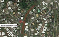
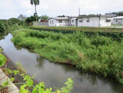
Over the past 40 years, high-flow events in the Kaneohe Stream have caused progressive erosion and degraded streambank integrity in north-central Kaneohe on the Hawaiian Island of Oahu. The problem along the eastern bank was exacerbated after a concrete lining was installed along the western bank in order to protect residential properties there.
Project Development
Initial geotechnical design for reconstructing and vegetating the streambank was based on a compost-sock structure with included geogrid wraps to provide a geosynthetic-reinforced “wall” ranging from 4 to 8 feet high. ParEn Inc., dba Park Engineering of Honolulu, HI, was responsible for civil design and developed the construction drawings and specifications. STRATA Inc. of Boise, ID, conducted the geotechnical fieldwork, soil testing, and geotechnical design of the wall.
Geotechnical Evaluationand Design
Due to limited equipment access to the project site, geotechnical investigation and sampling relied on hand tools (such as a post-hole digger) that allowed for excavating three test pits to a maximum depth of 3.7 feet (1.13 meters) to identify and describe subsurface soils. Laboratory testing included the following:
- Natural Moisture Content & Dry Density—ASTM D2216, ASTM D2937
- Particle-Size Analysis—AASHTO T-27 and ASTM D1140
- Atterberg Limits (liquid limit and plasticity)—ASTM D4318
- Classification of Soils for Engineering Purposes—ASTM D2487
- Direct Shear Strength of Soil—ASTM D3080
- Laboratory Compaction Characteristics of Soil (Maximum Dry Density and
- Optimum Moisture Content)—ASTM D1557
For geosynthetic reinforced-soil wall design, the focus is on evaluating engineering stability against the following potential failure modes (Koener, 1998, Berg et al., 2009):
- base sliding
- overturning (i.e., rotational tipping of the wall)
- exceeding foundation bearing capacity
- internal failure of the geogrid (i.e., rupture or pull-out)
- large-scale global slope failure
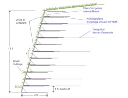
All of these potential modes were checked and evaluated using accepted geotechnical stability analyses, which showed that standard design criteria were met for a wall system 5 to 8 feet high, with 4-foot wrap embedments of PYRAMAT-75, and with an overall face angle of 1H:3V (71 degrees) which included a mid-height step to be used as a planting bench.
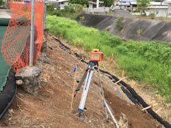
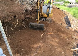
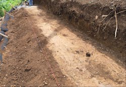
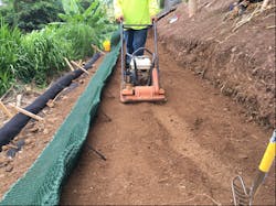
Site Grading and Subgrade Preparation: Because this geosynthetic wall system must be founded directly on native soil or approved structural fill, subgrade preparation involved vegetation removal and grubbing, followed by using a mini-excavator with smooth-blade bucket to remove topsoil and organic detritus in order to reach native, undisturbed soil (Figure 4) and provide a smooth platform to place the initial wrap-face lift. Line and grade for the wall base were surveyed and marked with paint or string-line.
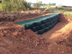
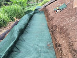
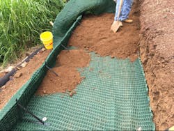
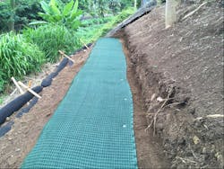
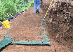
Wrap-Wall Construction: The HPTRM roll width of 8.5 feet (2.6 meters) allows for a bottom width of 4 feet, a lift height of 1 foot, and a top-flap layback width of 3.5 feet. After the internal braces were installed at a regular 24-inch spacing, the long section of HPTRM was placed on the level pad, the front edge properly aligned, then the fabric stretched taut in both directions and pinned down (Figure 6). Backfill soil then was placed and spread, then compacted in two 6-inch lifts (Figure 7) to fill the wrap-lift to the brace height.
Because the HPTRM wrap-face system is flexible, the curve required by the wall alignment was achieved easily for each successive lift by cutting the horizontal HPTRM sections perpendicular to the wall face, and then overlapping the cut fabric accordingly to match the curve shape.
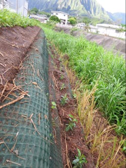
During the construction period of July to October 2018, the site was affected by minor flooding due to Hurricane Lane in late August. The high flow in Kaneohe Stream reached the base of the wall pad but did not cause any damage to the partially constructed wrap-face wall. However, the heavy rainfall and wet site conditions caused a work delay of about two weeks while waiting for the soil to dry out and allow proper compaction again.
If needed, temporary irrigation can be used to help new plantings get established. For shoreline applications, lower wrap-lifts planned to be below average water level may be filled with coarse granular backfill (to allow free movement of water), then overlying lifts transition to finer-grained infill soil above the waterline to support wetland vegetation. This wall system also is ideal for saltwater applications using brackish-tolerant plant species, because the geosynthetic components are chemically inert and do not corrode.
By using internal seeding and post-seeding via hydroseeding, excellent grass cover can be established quickly even in northern climates, as shown by a similar wall constructed near St. Paul, MN, in 2019 (Figure 11).
References
Berg, R.R., B.R. Christopher, N.C. Samtani, 2009. Design of Mechanically Stabilized Earth Walls and Reinforced Soil Slopes. Publ. No. FHWA-NHI-10-024 and 025; USDOT, Federal Highway Administration.
Koerner, R.M., 1998. Designing with Geosynthetics, 4th Ed.; Prentice-Hall.
Miller, S.M., 2016. “Breakthrough Technology for Vegetated Retaining Walls and Slopes Using Internally Braced, Wrapped Geosynthetic Structures.” Environmental Connection 10(3): 21–25.
Miller, S.M., 2017. “Internally Braced, Geosynthetic Wrap-Face Vegetated Walls and Reinforced Soil Slopes,” Geosynthetics, Vol. 35, No. 5: 24–33.
Miller, S.M., & D. Loizeaux, 2019. “Highway Embankment Construction Using a Geosynthetic Wrap-Face Vegetated Wall System,” Proceedings, IFAI Conference, Houston, TX, (Paper No. 1222): 793–803.
Stanley Miller
Stanley Miller is professor emeritus, Department of Civil Engineering, University of Idaho, currently working part-time as an independent engineering consultant. He has over 35 years experience in geotechnical engineering, slope stabilization, geosynthetic-reinforced earth structures, and erosion and sediment control.
