About the author:
Steve Cooper is a writer for SCA Communications. Cooper can be reached at [email protected].
by Steve Cooper
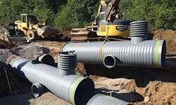
undefinedAs part of the ongoing Combined Sewer Overflow (CSO) program, the surcharging of one lift station was solved by using long, parallel runs of large diameter pipe instead of replacing or enlarging the lift station.
North Vernon, located on the Muscatatuck River in the southeast corner of the state and just north of the junction of Indiana, Kentucky and Ohio, embarked upon a multi-phase, CSO Long Term Control Plan (LTCP) that would be implemented during the next 10 years.
The North Vernon collection system has approximately 38 miles of sewer pipe of which approximately 60% is combined. There are 20 pump stations which feed into three main trunk lines. Four of these lift stations may experience surcharging during significant rain events including the Southwest Lift Station — Lift Station Number 22 — which would overflow a number of times a year. It has three pumps, each with a flow of 634 gallons per minute (gpm), to service 988 acres and is the largest of the 21 stations in the system. The new pipe system temporarily stores wet weather volumes upstream of the lift station. The water will then flow from the pipes to the lift station and be pumped to the treatment plant. The pipeline was designed to handle a 10-year, one-hour event, which required a storage volume of 128,000 gallons - a capacity that also took into account the existing pumping capacity. The new pipe system actually provides more than 147,000 gallons of storage.
"The advantage of this offline storage detention system is its relative simplicity," explained Michael Gangstad, P.E., senior project engineer for Lochmueller Group Inc. (Evansville, Ind). "It's a passive, gravity-flow system. There are no mechanical or electrical controls. And the operation and maintenance costs are low. The other advantage to this alternative is the ability to reuse the facilities. The existing wet well, valve vault and force main will remain in operation."
When the capacity of the North Vernon sewer system or the wastewater treatment plant (WWTP) was exceeded, such as during a heavy rainfall, excess water would be occasionally allowed to overflow directly to surface water bodies, including the Vernon Fork of the Muscatatuck River, through the CSO outfall listed in the city’s National Pollutant Discharge Elimination System (NPDES) Permits.
According to the U.S. Census, North Vernon's population is approximately 6,700 within its nearly three square miles. The city's wastewater is treated by a 2.2 million gallons per day (mgd) (average design flow) activated sludge-type wastewater treatment plant with a peak design flow of 4.76 mgd.
The North Vernon Wastewater Collection System was built in the 1930s. In the late 1950s, the city expanded both its collection and treatment systems by constructing approximately 22,500 linear feet of 12 inch to 36-inch interceptor sewer, two lift stations, a main intercepting chamber and a 24-inch interceptor sewer. Seven overflows were constructed. The sewers built during this project were designed and constructed as combined sewers. The treatment and collection systems were expanded and upgraded again in the late 1970s.
"The Southwest station was the one where they had trouble with overflows," Gangstad said. "It was the most troubling one in the system and would overflow a number of times a year due to the size of the sub-basin that was feeding it. It's a combined sewer system that is feeding that pump station....a pretty large one."
Gangstad and his team did an extensive evaluation of the situation.
"First during the study phase, we gathered flow monitoring data from the 18-inch diameter pipe coming into the lift station," he said. "We got months and months of data, and with that data we were able to develop a computer model of that sub-basin and calibrate it. That gave us an accurate model of what was out there and then we were able to design and figure out the capacity of the water that needed to be temporarily stored.
"We calculated the ultimate volumes we needed to store during a wet weather event. We wanted the pipe to empty by gravity — we didn't want to put pumps on the 48-inch pipe because that would have defeated the whole purpose. Because of the elevation of the existing piping and the ground surface, we were limited to that height and couldn't go any bigger than 48 inches. We just figured out how long and how much pipe would be needed to get to that total volume. It ended up being 1,600 linear feet in a parallel configuration."
The pipe used was ADS SaniTite HP polypropylene pipe, which is approved by the Indiana Department of Environmental Management. At project completion, the system was tested with zero leakage. SaniTite HP pipe is a product of Advanced Drainage Systems, Inc. (ADS) (NYSE: WMS).
SaniTite HP pipe in 12- to 60-inch diameters provides a smooth interior and exterior wall design supported by a corrugated structural core for stiffness and beam strength to minimize deflection and enhance long-term performance. SaniTite HP pipe meets ASTM F2736, ASTM F2764 and exceeds ASTM D3212 for water tightness with dual-gaskets and banded reinforced bell.
"SaniTite HP pipe is a lot less expensive than the equivalent in concrete pipe or any other pipe that would meet our specifications." Gangstad said. "Price was really the driving factor there. The team allowed RCP but for a sanitary application, it was at least 50% more or even closer to double the cost. The system had to be watertight because it's a sanitary application. And that pipe had the gaskets to do that."
Gangstad's design called for twin 316-foot runs of pipe for half the design and then three, 335-foot lines further upstream. A total of 1,600 feet of 48-inch diameter pipe was used. There are eight risers and cover ranges from three to four feet. Backfill and bedding was #8 stone. Prior to adding backfill, the pipe was overlaid with geotextile to prevent any floatation due to the high water table. Fabrication of all fittings was done at the ADS manufacturing plant.
Water stays in the detention pipe system for one or two hours depending on the severity and volume of rain. It flows to the station then to another sub-basin and then by gravity to the treatment plant.


