About the author: Steven D. Trinkaus, P.E., is principal engineer for Trinkaus Eng. LLC. Trinkaus can be reached at [email protected] or 203.264.4558.
Steven D. Trinkaus
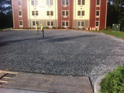
undefinedAbove: Gravel surface prior to installation of the permeable pavement.
Low impact development (LID) treatment systems commonly are used to reduce pollutant loads in runoff and provide groundwater recharge for small, frequent rainfall events. However, in certain situations, these LID systems also can be designed to provide peak rate and runoff volume attenuation up to and including 100-year rainfall events.
Design Parameters
This project consists of a residential apartment building with associated parking area in a community that requires there be no increase in runoff volumes for storm events from the 2-year to the 100-year event for all development projects. The apartment building has 36 units and a footprint of approximately 8,000 sq ft. The parking area consists of 45 parking spaces with a total area of approximately 18,000 sq ft.
Site soil investigation was necessary for the design of the LID systems, which were modeled using HydroCAD to meet the municipal storm water requirements. Installation of those systems required a specific construction sequence.
The site is 3.6 acres in size with an upland knoll of 1.4 acres in its approximate center. The highest point of the knoll is about 8 ft above the elevation of the wetlands around the site. The remaining 2.2 acres consist of delineated inland wetlands and are part of a contiguous, more-than-30-acre wetland system. Initial plans for the design of the storm water management system focused on water quality and groundwater recharge, as any increases in the peak rate of runoff would be attenuated in the large wetland area. During a preliminary meeting with the municipal land use staff, it was stated that a recently adopted policy required no increase in runoff volume from the 2-year up to and including the 100-year rainfall event.
Installed bioretention cell and overflow spillway.
Site Investigation & Design
A series of deep test holes were excavated on the site, revealing well-drained, sandy loam underlain by coarse sand and gravel. The test pits were excavated to a depth of 12 ft, which was below the surface elevation of the wetlands, and no groundwater was encountered. This demonstrated that the surface water in the wetlands was sealed off from the sand and gravel by the surface soil layer in the wetlands.
Double ring infiltration tests were conducted in both the sandy loam and sand and gravel soil layers. The sandy loam layer had an average infiltration rate of 4 in. per hour and the sand and gravel layer had a minimum infiltration rate of 10 in. per hour.
As the soils were suitable for infiltration, it was determined bioretention systems for the roof runoff and asphalt permeable pavement for the entire parking area would be used.
One bioretention cell was located in the rear of the building and another was located near the front corner of the building. Half of the roof area was directed to each bioretention cell. The entire parking area was to be constructed using permeable asphalt pavement.
LID & Construction
The bioretention systems were sized to fully contain the required water quality volume from the contributing impervious area with a maximum ponding depth of 24 in. The infiltration rate was not factored into the sizing of the storage volume, as it provides a factor of safety to handle larger rainfall events. In using HydroCAD to model the bioretention systems, 50% of the observed infiltration rate was used. In this case, 2 in. per hour was the exfiltration rate. The model was run for all the required rainfall events and demonstrated the bioretention systems would fully infiltrate the runoff volume from up to the 100-year event without exceeding the designed maximum ponding depth.
The permeable pavement system was designed utilizing the cross section developed by the University of New Hampshire Stormwater Center, but the stone reservoir layer was not used due to the presence of the well-drained sand and gravel soils. The gravel base under the asphalt layer was 15 in. deep, which is not a significant increase over the standard depth of 12 in. This system was modeled in HydroCAD using an infiltration rate of 1 in. per hour, or 10% of the observed rate. The results showed that all of the rainfall from a 100-year event would be fully infiltrated with a maximum ponding depth of 2 in. in the base of the gravel layer.
A common construction error with the installation of bioretention systems is installing them at the end of the construction period and then introducing storm water to them before the vegetation has become established. In this case, the two bioretention systems were installed just after the foundation was installed. The bioretention cells were fully graded and planted, so that when the roof drains were installed to the bioretention systems, they were ready to accept storm water.
The permeable pavement, on the other hand, was installed at the end of the construction period so there would be no movement of heavy construction vehicles on the permeable surface.
The gravel base beneath the asphalt layer is 15 in. deep.


