The only best management practice (BMP) that creates optimal conditions for removing significant amounts of sediment from runoff waters is a properly designed, installed, and maintained sediment basin or trap (Figure 1). Also known as sediment containment systems (SCSs), these designed structures have the potential to remove 75% or more of the suspended solids found in runoff waters.
It is possible to estimate parameters of an effective SCS without complex equations. This requires incorporating an optimal geometric shape, providing enough detention time for suspended particles in runoff waters to fall, ensuring that adequate fall distances exist and assessing flood flow discharge conditions.
Important features of an effective construction site SCS include the following:
- Inflow and outflow values must reflect design flood flow conditions.
- The design-size suspended particles to capture must be identified.
- Long internal flow path lengths within contained runoff waters must exist.
- There must be long detention times (e.g., 36 hours or longer) to drain contained waters.
- The SCS must provide a minimum treatment runoff volume.
- Storage volume for deposited sediments must exist.
Long flow distances within an SCS are necessary to capture suspended particles falling through the water column. This can best be accomplished by designing SCSs to incorporate a rectangular shape. Circular and square shape SCSs will require internal baffles to achieve the effectiveness of a properly designed rectangular shaped structure.
Effectiveness of an SCS
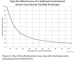
The effectiveness of an SCS to capture suspended particles in runoff waters is dependent upon the rate of discharges from the structure. Maximum effectiveness only occurs when all runoff waters are retained. When part of a large detention pond, an SCS may have a high effectiveness to capture small (e.g., 20-micron) suspended particles during low discharge events. However, when flood flows enter and discharge from an SCS, the effectiveness to capture small suspended particles is usually low.
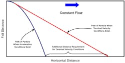
Figure 2 illustrates when suspended particles have a significant mass (e.g., large sands, rocks, and pebbles) they accelerate downward through water due to gravity. Smaller suspended particles having small mass encountering fluid resistance may not accelerate and may, instead, fall through the water column with a terminal velocity.
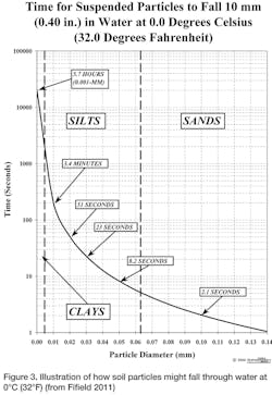
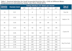
Figure 3 illustrates estimated times for different size particles to fall 10 millimeters (0.40 inches) in a water column as calculated by Stokes’ Law (Table 1). Notice how small colloidal particles (e.g. clays) take an extensive amount of time to fall 10 millimeters (0.40 inches) when compared to larger sized particles (e.g., sandy material). It is for this reason that capturing fine silt and clay colloidal particles is difficult.
Extremely small colloidal particles may be subject to Brownian Movement and can remain suspended for long periods of time. Particles that are larger in diameter accelerating through water do so according to Newtonian laws of physics.
Parameters for an Effective SCS
The more commonly found SCS on a construction site is a structure that detains runoff waters. Sediment basins/traps are usually detention structures that slowly release contained waters. An effective SCS must accommodate both slow discharges and flood flows from the system.
Minimum containment volume is often cited as the only criteria for designing an SCS. This is a major misconception since discharge rates, internal flow velocities, internal flow distances, design-size particles to capture, and pond surface area are more important.
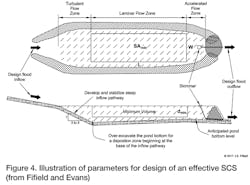
Figure 4 provides a conceptual illustration of an SCS to develop parameters for implementing effective sediment basins/traps on an active construction site. The following assumptions apply to this drawing:
- Inflow must equal outflow values for design flood discharge conditions.
- Large suspended particles are captured within the turbulent flow zone during flood flow events.
- Smaller suspended particles are captured within the laminar (i.e., smooth) flow zone.
- Within the laminar flow zone during flood flow events, a minimum containment volume is approximated by a rectangular solid.
- Effectiveness of the SCS is directly dependent upon discharges from the system.
Maximum effectiveness of an SCS will occur when contained runoff waters are totally retained. However, retention ponds are not practical for construction sites. Thus, most sediment basins are detention structures.
When detained waters take a long time (e.g., at least 36 hours) to drain, the structure’s effectiveness can be high. However, during high flood discharges, low effectiveness exists (Figure 5). Thus, the design of a sediment basin/trap should not be limited to only calculating inflow volumes of runoff per unit area. Flood flow discharges must also be incorporated into all SCS designs.
Importance of Discharge
A uniform internal flow velocity is necessary to capture sediment from runoff waters discharging from an SCS, especially during flood flow conditions. It is within the laminar flow zone where a uniform internal flow velocity will likely exist, which is not always easy to determine (Fifield 2011).
An indirect method of “estimating” the effectiveness of an SCS is to evaluate the impact of releases since internal flow velocities are dependent upon discharge rates. Only when low discharge rates exist will the potential of maximum effectiveness exist to capture very small suspended particles.
It is necessary that the effectiveness of an SCS be determined for both controlled (i.e., slow) and flood discharge conditions. Controlled discharge rates are those associated with use of a skimmer, riser pipe, or other methods. It is suggested that flood discharge rates over a spillway be represented by at least a two-year, 24-hour runoff event.
Containment volumes of runoff within the laminar flow zone having significant amounts of silts and clays need at least 36 hours to drain. Maximum effectiveness in removing sediments from contained runoff waters occurs by using a skimmer to slowly remove water from the upper layers of a pond. It is at the surface of a containment pond where minimal amounts of suspended solids reside.
Minimum Laminar Flow Zone Containment Volume
An effective sediment basin/trap must contain enough runoff to ensure the trapping of sediment. The USEPA (1991) suggested a minimum containment volume by assuming 75 millimeters (3.0 inches) represented a two-year, 24-hour rainfall event for the US that resulted in 25 millimeters (1.0 inch) per unit area of runoff and 50 millimeters (2.0 inch.) per unit area of infiltration. Runoff of 25 millimeters (1.0 inchs) per unit area is equivalent to a volume of 250 cubic meters per hectare (about 3,600 cubic feet per acre). Such runoff and infiltration values are only associated with HSG A (i.e., sandy) soils.
USEPA also suggested that 90% of all rainfall events falling on any type of soil will result in no more than 25 millimeters (1.0 inch) of runoff. This suggestion has some validity, but requires an update.
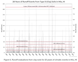
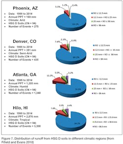
Simulations of runoff values were modeled by the NRCS Curve Number Method to assess the impacts of rainfall on HSG D soils in different climatic conditions (Figure 6). The results suggest that about 90% of all runoff events rarely exceed 38 millimeters (1.5 inches) per unit area. Figure 7 illustrates simulated runoff values from HSG D soils in four different climatic regions.
By evaluating results of data assessments at different climatic regions and incorporating requirements for an effective SCS, the following minimum laminar flow zone runoff containment volumes (Volmin) are suggested using Trewartha Climatic Classifications (Trewartha and Horn 1980):
- Volmin = 125 cubic meters per hectare (1,800 cubic feet per acre) for dry (a.k.a. arid and semi-arid) climates,
- Volmin = 250 cubic meters per hectare (3,600 cubic feet per acre) for temperate and continental (a.k.a. humid) climates, and
- Volmin ≥ 380 cubic meter per hectare (5,450 cubic feet per acre) for sub-tropical and tropical climates.
A larger runoff volume for sub- and tropical climates is necessary since a greater number of rainfall events happen that result in increased runoff occurrences. Statistical assessments of local rainfall data should be completed to verify whether the aforementioned values are applicable to local climatic regions and soil conditions.
Estimating Laminar Flow Zone Parameters
Fifield (2011) and Fifield and Evans (2018) suggest the following equations for estimating laminar flow zone parameters when uniform internal flows exist:
- Minimum Laminar Pond Surface Area:
SAmin = L x W = Qoutflow ÷ Vterm Equation 1 - Laminar Flow Length:
L = (L:W x SAmin)0.5 Equation 2 - Minimum Laminar Containment Volume:
Volmin = dmin x SAmin ≥ 125 cubic meters per hectare (1,800 cubic feet per acre) Equation 3
Where:
dmin = Minimum pond depth ≥ 750 millimeters (30 inches)
L = Flow length of rectangular volume (meters or feet)
W = Width of rectangular volume (meters or feet)
L:W = Length-Width Ratio ≥ 3.0
Qoutflow = Discharge rates from the SCS (cubic meters per second or cubic feet per second)
Vterm = Terminal velocity of design-size particles (meters per second or feet per second)
Assessing Pond Surface Areas
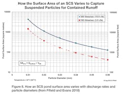
Figure 8 illustrates how pond surface areas vary to capture suspended particles for different sediment-laden discharges. Notice that as the diameters of suspended particles become smaller, larger surface areas become necessary. Conversely, capturing suspended particles that are larger in diameter can be accomplished with smaller pond surface areas. For example, pond surface areas for capturing 40-micron suspended particles are more than 90% smaller than what is necessary for trapping 10-micron particles.
The design of a sediment basin/trap must reflect what happens during flood flow conditions. Once this baseline is established, the effectiveness of an SCS to capture suspended solids will increase as flood discharges decrease. Designing a sediment basin/trap using flood flow conditions also ensures development of sufficiently large pond surface areas to capture suspended particles in inflow runoff waters.
Estimating Sediment Basin/Trap Parameters
A review of Figure 4 will demonstrate that parameters of an SCS will likely be different from what is found by Equation 1 through Equation 3. For example, actual surface area of the pond will be larger than the laminar flow zone area. As a result, longer internal flow lengths and deeper pond depths may be necessary.
Due to the variability of an SCS structure, the following equations are suggested in order to estimate the parameters of a sediment basin/trap when Lscs:Wscs ≈ L:W and adjustment factors of Ψ1 ≥ 1.0 and Ψ2 ≥ 1.0 are considered.
- Estimated Surface Area:
SAscs ≈ Ψ1 x SAmin Equation 4 - Estimated Length:
Lscs ≈ (Ψ1)0.5 x L Equation 5 - Estimated Width:
Wscs ≈ (Ψ1)0.5 x W Equation 6 - Estimated Depth:
dscs ≈ Ψ2 x dmin Equation 7 - Estimated Containment Volume:
Volscs ≈ (Ψ1 x Ψ2) x Volmin Equation 8
Example Calculations
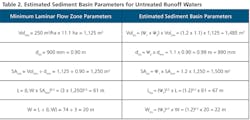
What are the estimated parameters of a sediment basin/trap to capture sediment in runoff from 4.5 hectares (11.1 acres) of bare ground flowing into the structure when the design flood discharge for a two-year, 24-hour event is 235 liters per second (8.3 cubic feet per second)? Table 2 summarizes estimated SCS parameters when a runoff water temperature is 10°C (50°F), temperate climatic conditions exist, L:W = 3.0, dmin = 900 millimeters, and the adjustment factors are Ψ1 = 1.2 and Ψ2 = 1.1. It is important to note that values in Table 2 represent estimated parameters for a sediment basin during a specific design flood flow discharge event. When this occurs, the SCS effectiveness to capture suspended sediments will likely be low but will increase as flood flow conditions lessen. More information on how the effectiveness of an SCS can be enhanced using porous baffles and introducing flocculants into runoff waters can be found in the work by Kang et. al. (2014).
Applicability to Flocculant-Treated Runoff Waters
A distinct disadvantage of using results of Equation 1 through Equation 8 for untreated runoff waters is that an effective SCS structure requires long flow lengths to provide enough fall time to capture very small and fine sized suspended particles. Figure 3 demonstrates that the fall time for sediments suspended in contained waters is small when capturing large diameter suspended particles.
When flocculants are added to runoff waters, “flocs” are created that fall through the water column with a large terminal (or accelerated) vertical velocity due to an increase in mass. As an example, when flocculant treated runoff waters create flocs that simulate the fall rate of at least 30-micron size particles, the material may have a net estimated terminal velocity (see Table 1) of about 60 x 10-5 meters per second (200 x 10-5 feet per second) at water temperatures of 10°C (50°F).
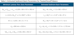
Table 3 illustrates how to estimate parameters of a sediment basin/trap when incorporating information from the previous example and assuming “floc” material simulates a 30-micron size particle. In this example, Ψ1 = 1.2 and Ψ2 = 1.3.
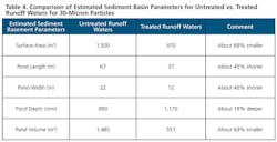
Table 4 provides a comparison of estimated SCS parameters when flocculants are added to runoff waters and assuming the fall rate of a floc simulates a 30-micron size particle.
Much more research is needed to assess the impact of flocculants to enhance the effectiveness of sediment basin/trap parameters. For example, how small can SCS structures become and still be effective in capturing “flocs” that simulate fall rates of larger diameter design-size suspended particles? Also, do environmental issues exist with anionic flocculants as may exist with cationic materials?
Summary
The design of a sediment basin/trap is much more complex than simply capturing a specific volume of runoff from contributing watersheds. Developing parameters for an effective sediment basin/trap must consider the following:
- Flood discharge rates, which dictate the effectiveness of an SCS to capture sediments,
- Internal flow velocities, which impact the effectiveness of an SCS to capture sediments, and
- Design-size particles to capture.
By incorporating the above limitations into a sediment basin/trap design, the following parameters represent what must be incorporated (in a suggested order of importance) into designing effective structures to remove suspended particles out of runoff waters:
- Controlled discharge rate for contained runoff waters,
- Flow length and structure width,
- Minimum fall distance for suspended particles,
- Surface area of the containment pond, and
- Minimum containment volume.
The following minimum sediment basin/trap containment volumes are suggested for capturing untreated runoff waters:
- Volmin = 125 cubic meters per hectare (1,800 cubic feet per acre) for dry (a.k.a. arid and semi-arid) climates,
- Volmin = 250 cubic meters per hectare (3,600 cubic feet per acre) for temperate and continental (a.k.a. humid) climates, and
- Volmin ≥ 380 cubic meters per hectare (5,450 cubic feet per acre) for sub-tropical and tropical climates.
A series of equations are presented to estimate sediment basin/trap parameters for design flood flow conditions. The equations are suggested to be applicable for development of structures to remove suspended sediments from non-treated or flocculant treated runoff waters.
References
Environmental Protection Agency (EPA). 1991. Proposed Guidance Specifying Management Measures for Sources of Nonpoint Pollution in Coastal Waters. EPA Number 841B91109. Office of Water, Washington, DC 20460. May
Fifield, Jerald S. 2011. Designing and Reviewing Effective Sediment and Erosion Control Plans. Third Edition. Santa Barbara, CA: Forester Media.
Fifield, Jerald S., and Tina R. Evans. Developing Effective Storm Water Pollution Management Plans. Santa Barbara, CA: Forester Media. Publication pending.
Kang, J., S.E. King, and R.A. McLaughlin. 2014. “Impacts of Flocculation on Sediment Basin Performance and Design.” Transactions of the American Society of Agricultural and Biological Engineers, 57(4): 1099-1107.
Trewartha, G.T., and L.H. Horn. 1980. An Introduction to Climate. 5th edition. New York, NY: McGraw Hill

