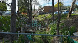
Traveling along Madison Street, drivers in Sioux Falls, SD, can enjoy the view of the small but pretty manmade Covell Lake. The road bisects the lake, so the water is present on either side of Madison Street.
The problem was that the lake was experiencing erosion along its north and west sides.
To stabilize the shoreline, various options were considered by the city. Among them were sheet pile walls, reinforced concrete walls, and segmental concrete walls.
“These walls may have worked for some portions of the shoreline, but not in others,” says Jon Hansberger, director of engineering for ReCon Wall Systems, based in St. Louis Park, MN. “What they found with borings is that about 16 to 20 feet down there was real lean clay, silty clay. In other spots, there was granite. We actually got involved pretty early in the project. They had used ReCon on a previous project, and they thought that this might be a good solution here.”
He notes, “They wanted to go with the big blocks, the wet-cast blocks, because of their durability and because they would be sitting in water. There’s a constant water level up on the wall. It was important to be able to specify a 4,000-psi concrete with 5.5% to 7.5% air entrainment.
“They actually came in and filled in a portion of the lake, going out about 50 feet from the road, and put in a silt barrier, which gave us access to the lake. We came behind there and trenched out where the wall was going to go. We had to dewater that area during construction, so we basically constructed a berm between the lake and where the wall was going to be.”
To replace riprap, which had originally been present, a ReCon gravity wall was built, due to the structural limits of being close to the roadway. “It is supported either on granite or on a geopier impact system,” Hansberger explains. “It’s backfilled at a 45-degree angle, with crushed granite, because the water is going to get up on the walls and get in between the blocks and behind the wall. There are subtle fluctuations where the water is allowed to get in and drain out of that wall system.”
The retaining wall stands approximately 8 feet high, and extends for 550 feet along the northern and western edges of the lake.
Once the basic wall was constructed, the contractor positioned a backhoe on the ground above the back side of the wall to remove the dirt from immediately in front of the wall. That allowed workers to stain it and apply a sealer, and even an anti-graffiti coating. Once that was completed, they removed the rest of the dirt berm in front of the wall, permitting the water to return and wash up against the wall.
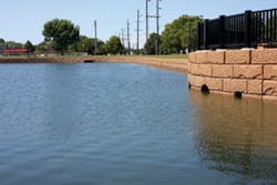
Hansberger notes that the wall is vertical, with most of it underwater. “There’s only about 4 feet of it sticking out. Then there’s a little observation deck on top at one end, with a railing. You see a lot of people fishing off the wall into the lake.
“One of the other unique things we did on this project was to pour a cast-in-place headwall for three pipes that come through. And we put a granite liner on that matched our block texture.”
Limited maintenance is required. “There’s not really a lot of flow on this wall, so we’re not really worried about scour. They did put a barrier at the wall and riprap at the toe, where water might come up and down on the wall. There might be a time when you want to check for low water conditions if any area is exposed. But this has a pretty steady water level, so there really isn’t a whole lot of maintenance associated with this application. That is, unless somebody comes out and spray paints it-then you’ve got to clean it off.”
He adds, “I was out there on a fishing trip with my daughter’s class, and it looked pretty good. have occasionally seen a weed or two come through the wall, but there’s general maintenance that comes in and cleans those things out. It looks as good now as when it was finished.”
Detention basin for flood control
Controlling Flash Flooding in Arizona
In parts of Arizona, rain can be scarce, but when it comes, it can come in sudden torrential downpours. Mohave County, in the northwest portion of the state, is such an area.
“We may only get an inch during a rain event, but it could come in a span of 30 minutes,” says Nathan Angel of Oldcastle Superlite. “The ground can’t accept it that fast, so all the natural washes start to run. The biggest challenge in this area is that this was regularly threatening the surrounding neighborhoods.”
The sudden flash floods were also causing significant erosion and sediment runoff from the hills surrounding Lake Havasu in the area. To combat these issues, the county commissioned the construction of detention basins and flood control channels.
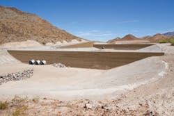
Approximately 210,000 cubic yards of soil had to be excavated from the project site to create detention basins sufficient to accommodate up to 74 acre-feet of water, equivalent to the runoff from a 25-year storm. The detention basins required battered walls, while the flood control channel utilized near-vertical walls.
Angel explains that originally another supplier was selected for the project. When it became apparent, however, that with that supplier, two different materials would have been required for the two types of walls, the contractor approached Oldcastle. As a result, the product specifications were ultimately changed to provide for the use of Keystone retaining walls, for which Oldcastle is the licensed manufacturer in Arizona.
The battered walls were required for extra strength in the detention basins. “But for the vertical walls, there wasn’t as much a need for strength,” Angel says. “Rather, it was a matter of working within the confined area. Without having the batter, they were able to work in a narrow location.”
He also explains that the coarse, granular soil found at the site proved beneficial for the project. “They didn’t have to haul off any dirt, and they didn’t have to import any dirt, which is always beneficial when you’re a retaining wall installer.”
The Keystone retaining walls extend as much as 2 to 3 feet underground, with quite a bit of Stratagrid geogrid reinforcement used. They reach a height ranging from 5 feet to 25 feet, with some 64,000 square feet of wall installed altogether.
Construction began in the summer of 2012 and was completed in January 2013. The design has worked to perfection, detaining the sudden rush of water when it comes, then slowly releasing it into Lake Havasu.
Protecting the Railroad
In mountainous regions where railroad tracks are vulnerable to the devastating effect of avalanches, protective structures known as snow sheds are sometimes constructed over the tracks. These allow tons of snow or water to pass over the structure, leaving the railroad tracks undamaged.
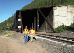
About a hundred years ago, the Great Northern Railway Co. built a series of snow sheds at the southern edge of Glacier National Park in Montana, where the railroad tracks run just above Highway 2. The BNSF Railway Co. currently owns those tracks and snow sheds.
“We’ve had some pretty big avalanches that bury the snow sheds under up to 30 feet of snow,” explains Dr. Bill Gates, chief geotechnical engineer for Jacobs Associates in Seattle. “Large watersheds are above each snow shed that capture surface water flow from the mountain basin above. Over the years they worked fine, but erosive elements began taking their toll.
“The ditches that were constructed to divert water flow around the snow sheds eventually became plugged by erosional debris. Subsequently, the streams followed the avalanche tracks over the snow sheds. The problem with the streams is that the water drips through the roof of the snow sheds and fouls the tracks, creating large mud pits. This reduces the ballast support to the railroad ties, causing them to break down and fail.
“So BNSF designed a system where we can capture the water, which would go into culverts, but they were designed so that avalanches would go across the sheds, parallel to the culverts, and not take the culverts out.
“We excavated a berm and a basin. We lined the basin with riprap and similar material and put in some heavy-duty culverts that go parallel to the flow of avalanches on top of the sheds, and drop down into the natural drainage.
“On the uphill side, we have a drop box for the water to flow into. On top of the riprap, once we put the soil in there, we secured everything with TECCO mesh from Geobrugg and tied it down. This way, when avalanches and water come down, the riprap and the bolted-down TECCO mesh will keep the berm from eroding away, and the water will be diverted into the drop boxes while the avalanches will go over the top.
“The TECCO mesh was the final safeguard, to protect the berm, the riprap, and the soil around it, and to strengthen the whole thing. And then it was hydroseeded.”
Gates says that the design stage began in 2012, with construction beginning in August 2013. It was completed in mid-October, with approximately 4,400 square feet of TECCO mesh used on the project.
One of the difficulties the construction team encountered was that they were not allowed to work inside the park boundary. “We only had a 100-foot right of way between the railroad track and the edge of the park,” he says.
Another challenge was the remoteness of the area, with no towns nearby. But one aspect of the project made matters a bit easier. “We dug a quarry pit right onsite, so we could transfer rock and soil material in order to create the berm. It was nice having this onsite instead of having to bring it in from some other location.”
Covell Lake, mid-construction with berm in place
Solving a Grave Problem
Major soil erosion can cause nasty problems wherever it is found, but when it occurs at the edge of a cemetery, it can be downright gruesome.
“After a major storm, the land was all sliding down the hill. With a few more rains, the coffins probably would have started popping out. So it was pretty much a rush situation to get that fixed,” says Phil Fassler, site consultant for Redi-Rock of Kentuckiana, based in Mt. Washington, KY.
“It just came to a head after they had a really good rain. There was a pretty good slope; it was just clay, so there was really nothing to hold it in place. It got loaded up with all that extra water weight, and there were repeated days of heavy rain, so it got more and more saturated until eventually something had to give under all that weight. That’s when they started having slide failure.”
The problem was occurring at Machpelah Cemetery in Mt. Sterling, KY. The Kentucky Transportation Cabinet (KYTC), responsible for the state’s roads, initially had considered poured-in-place concrete retaining walls to repair the slopes. However, KYTC decided that the aesthetics of a concrete wall wasn’t appropriate for a cemetery setting.
Covell Lake with completed wall
It was a well-timed Lunch ‘n Learn meeting with KYTC that involved Fassler and Redi-Rock with the cemetery project.
“It was just a matter of being in the right place at the right time. The slides had just started happening right before our meeting. They had been trying to figure out what they were going to do with it, and we showed up with a perfect solution, so they went with that.”
Because of the obvious need to minimize excavation, a gravity wall was used, involving 5,145 square feet of Redi-Rock 41-inch blocks, each weighing in excess of 2,300 pounds. No geogrid reinforcement was necessary. Each of the blocks has a knob-and-groove design, which means the blocks stack up like giant, 1-ton Legos.
On one side of the road along the cemetery, workers also incorporated a course of 9-inch setback blocks, used to increase the batter angle and allow taller gravity walls to be built. There were also corner blocks used as stepdowns as the wall transitioned down the slope, which can act as “speed bumps” for water runoff.
It took less than two weeks for the entire installation.
There have been multiple heavy rains since the wall was constructed, and there have been no problems, even though some of the storms have caused flash flooding in other areas nearby. You might say the neighbors can rest peacefully.
Back to School
As Hazel Grove Elementary School in Kansas City, KS, was being designed, a determination was made that the bus pickup lanes needed to be as close to the property line as possible.
George Schuler, project manager with the Judy Co., says his firm had constructed a temporary soil nail wall on the site as school construction was proceeding. “The school district had initially proposed an MSE [mechanically stabilized earth] wall to protect the bus lanes, but when they saw how quick and easy the soil nail wall was, they asked us to quote a price for a permanent soil nail wall.
“A soil nail wall does not require an excavation for the strap links like an MSE wall,” he says. “An MSE wall has geogrid straps, which actually hold the structure up. But these soil nail walls do not require the use of geogrid. So a soil nail wall requires less excavation, and this allowed us to get close to the property line. It also allowed us to go under some utilities-they didn’t need to be temporarily moved. Because of these factors, it was cheaper than an MSE wall.”
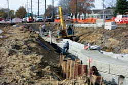
Schuler explains that a soil nail wall is dug into virgin dirt. “It’s top-down construction-you start at the top, make a cut 5 feet down at the back of the wall. Then you put the nails in, put temporary facing on, dig down another 5 feet, put more soil nails in, put construction facing on, and on down. When that wall is done, we call that the construction facing, and we put the reinforcement mat on. That’s when we called Boulderscape to come out and put the permanent facing on, and then carbon-stain it.”
The Boulderscape finish used was a random ashlar finish, with a medium earth-tone staining scheme that blended well with its surroundings, as specified by the project architect.
The finished wall, completed in less than a month, stands about 11 feet tall and extends for 520 feet.
An important requirement from the school board was that the wall finish had to be sculpted in such a way that the schoolchildren couldn’t climb on it. As a result, Boulderscape carved all the bedding joints with a 20-degree slope so that the kids would have a difficult time grabbing onto the joints. The joints were kept shallow and narrow to keep them from being used as hand-holds.
Route 52 Causeway Reconstruction
New Jersey’s Route 52 Causeway bridges dated back to 1933, and the state’s Department of Transportation identified four primary reasons for their replacement:
- Due to age, bridge decks were experiencing severe deterioration with substantial chipping and cracking.
- Highway traffic has increased, causing congestion on the causeway and its access roads and hampering access for emergency vehicles.
- Route 52 is an evacuation route from Ocean City, and waves from storms were frequently washing over lower sections, making them impassable.
- Accidents were occurring due to the Causeway’s narrow 10-foot lanes with no shoulders. Widening lanes to 12 feet and adding 8-foot shoulders was expected to reduce accidents by 20%.
Beginning in 2006 and finishing in 2013, the $400 million project involved replacing two fixed and two moveable bridges with two bridges that have two high fixed spans.
BNSF snowshed
The project was divided into two major phases, and Reinforced Earth Co., based in Vienna, VA, was selected as the supplier of MSE walls, temporary walls, and precast units for both phases.
One of the biggest challenges of the project was that settlement of walls into the sandy, organic soil layers was expected to be substantial.
“Because of the settlement, anticipated to be between 9 inches and 2 feet, two-stage walls were chosen for the areas with the greatest expected settlement,” according to Sherif Aziz, mid-Atlantic regional manager for Reinforced Earth. “Two-stage walls are formed by first building a wire wall. The wire wall is a retaining wall, but the wire facing is flexible. So when the wall settles, the wire wall deforms, but then it consolidates the soil underneath the wall.
“Then you come with the second stage of construction, by putting a nice concrete panel facing to it, kind of like a jacket cover. Whatever deformation you have in the wire wall is covered by these nice-looking precast concrete panels.”
Aziz explains that this settlement may typically take between 1 and 6 months to occur. After the wire wall is built, settlement plates are put down and monitored repeatedly until the settlement is seen to plateau. Once it has been determined that no further settlement is likely to occur, the contractor can move to the second stage, applying the precast concrete panels.
Single-stage walls were used in areas with anticipated settlements up to 9 inches, while the two-stage walls were selected for areas with greater expected settlement. Both single-stage and two-stage Reinforced Earth walls were designed for the bridge approach ramps on either side of the bay, as well as for the Visitors Center located on an island in the middle of the bay.
The first phase of the project used 23,400 square feet of MSE walls, all of which was single-stage. The second phase involved 25,600 square feet of retaining wall, 9,100 square feet of which was two-stage.
While MSE walls weren’t the only option for this massive project, Aziz explains why they were likely the best option.
“There are different types of retaining walls that could have been used. One is the cast-in-place, which is built with the old traditional cast-in-place reinforced concrete walls. Another possibility might have been a prefabricated modular wall, which is a system of big blocks that you place on top of each other, that create the bulk of the retaining wall.
“MSE is a compacted fill, and the reason it was chosen is that MSE is a very, very flexible retaining wall system. It’s also very cheap compared to the other alternatives. So it is economical and it is flexible, meaning that it can handle settlement without being exposed to any internal damage. It is also easier to construct, and you can have a very good architectural finish with these precast panels, so this wall combines a number of good advantages. Therefore, the consultants usually specify MSE walls.
“Because of the proximity to the ocean and the existence of flooding conditions, some of these walls were designed for flooding conditions. The 8.5 feet of water inside the wall itself has to be taken into account as well.
“The MSE walls also allow for a very, very quick drainage of water from the system. So whenever you have a flooding condition, and the water dissipates quickly from in front of the wall, the MSE panels that are placed have a lot of joints around them, so the water can get out of the MSE wall quickly without causing over-stressing to the body of the wall.”
Aziz further explains that obtaining proper backfill is crucial.
“They had to look for several sources, but there were a couple of quarries around the area where they were able to obtain backfill with properties that are suitable to our wall. You have to have a certain backfill with certain properties to be used in MSE walls. It has to be more of a granular material. You cannot have anything that has clay, or anything that has silt in it. It has to be mainly granular material.
“This allows the water to dissipate quickly. Another reason is that it gives a mechanical, frictional capacity to the backfill that bonds it with the reinforcing layers. The grains of the backfill interlock with the reinforcing elements, and this is what creates the bond. If you have clay or sand, they are very, very fine elements, and they don’t have the same frictional capacity that you would have with a very coarse material. The coarseness of the surface creates a higher frictional capacity.”
The infamous Hurricane Sandy struck the area in October 2012, but the bridge and its related structures remained intact and functioning properly. In fact, according to Aziz, a number of people used the bridge for emergency evacuation at the time, which it was intended to provide.
During the second phase of the project, constructing the walls for the visitors center, with its tiered pathways, proved more difficult. “The design there was very challenging because of the geometric nature of the pathways,” Aziz says.
“In addition, New Jersey is in a seismic zone, so we also had to consider seismic loading and flood loading. Two-stage is a very specific design, so that was also a condition that we had to take into account with the settlement. We had to calculate the settlement for each wall.
“This was a very complex job for us, but we were able to do a proper design for both phases. The contractors were very happy with our performance. Both contracts were
finished ahead of schedule. Everything functioned properly, and the DOT was very happy, since it all went as planned. It proved that the choice of using MSE was a good decision.
“The retaining walls look very, very nice. The project succeeded aesthetically, economically, and efficiently.”

