Mention geosynthetic materials, and there’s a tendency to think of the use of geotextile fabric strictly in terms of a turf reinforcement mat, an erosion control blanket, or silt fence. But even geotextile fabric is often used as part of larger engineered runoff-control systems-or in more heavy-duty applications such as scouring prevention. Geogrid, which must be included under the geosynthetics umbrella as well, often serves as the anchor for heavy structural protection systems. Geosynthetics sometimes are used in some unique, challenging locations where stability is needed, too.
A LEEDing Medical Center
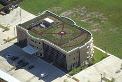
One recent unique application of geosynthetic materials was not at ground level but, rather, three stories high. The 251 East Medical Center in Webster, TX, is equipped with a 14,559-square-foot green roof-a key sustainable element in a building on track to be one of the first LEED (Leadership in Energy and Environmental Design) gold-certified buildings in the area. Careful consideration was given to choosing an underlayment and drainage system for the organic materials, and the performance of the roof to date has exceeded expectations.
Completed in January 2007, the 48,000-square-foot facility has considerable sustainability and aesthetic features. The roof features gardens, walking paths, and a lush landscaped area. Nearly three-quarters of rainwater that hits the roof is retained in order to sustain vegetation growth, while the remaining average of 24,000 gallons a month is transported to roof drains that direct it to underground cisterns for storage. That reclaimed water is used for purposes such as irrigation and flushing toilets.
Per-square-foot cost claims by green-roof system manufacturers that architect Joe Douglas Webb, AIA, of Webb Architects in Houston, and the building team deemed unrealistic led to the choice of the Colbond EnkaRetain & Drain system for the green roof. Team members attended GreenBuild 2005, the US Green Building Council’s annual convention in Atlanta, and several green-roof suppliers claimed that a conventional green-roof system was within the project budget of $10 to $15 per square foot. Actual estimates turned out to be $25 to $35 a square foot, so the team sought an alternate solution.
The green roof atop this Texas medical center is designed to move heavy rainfall quickly while retaining enough moisture for vegetation.
The chosen system is designed to have an R68 insulation rating and cost less than a conventional system, mainly by reducing installation time. A 4-inch layer of rigid foam insulation board with a protective coating was installed on the roof structure. A 40-mil reinforced waterproofing membrane was placed over the foam board to the roof sidewalls and drain assemblies. Last, the EnkaRetain & Drain retention composite was installed directly on top of the waterproofing membrane.
With the structure in place, a 9-inch-deep soil mixture was placed on top-a mixture specially developed by a local soil consultant according to proposed plant materials, water retention needs, and the wet weight limit.
The retention composite is designed specifically for green-roof and planter applications and consists of a post-industrial, recycled polypropylene drainage core that is fused and molded into a square waffle pattern. A super-absorbent water retention fabric is heat-bonded to a drainage core called Enkadrain and is designed to hold 10 to 12 times its weight in water. The fabric retains rainwater that keeps plant roots hydrated, while excess water drains through the core. Enkadrain exceeds 40% post-industrial recycled content and can contribute up to two LEED points when used with other recycled content building products.
Despite what appeared to be a sound design, Webb was skeptical. He was concerned that runoff would not be moved off of the roof in the event of a major downpour. So, he says, “I probably put about twice the number of drains on that roof-twice as many as you need if calculated the right number according to the building code. I had no experience with how well the stuff was going to flow to a roof drain over distances. But we have never had a problem.”
The manufacturer showed Webb research data demonstrating the efficacy of the materials on green roofs in Europe over several years. “Basically, they said that if it didn’t work, they would tear it up and replace it,” Webb says. “Would we have taken them up on that? Doubtful. But they showed us the flow calculations; I had no way to calculate them on my own.”
According to the installer, Jacob White Construction, using the combination of foam board, membrane, and EnkaRetain & Drain saved at least two to three weeks compared to installation of a proprietary system. In addition, the material cost savings alone were roughly $250,000.
But material costs do not account for the bulk of the savings compared with other systems, Webb contends. “I definitely think it’s labor-related,” he says. “[Colbond’s] product was probably 20% less.” Additionally, Webb indicated that the green roof is likely saving an undetermined amount of energy inside the building. He believes that, because the system always retains some quantity of water, the roof insulates the building from the outside via evaporative cooling. According to Webb, temperature readings at the bottom of the green-roof structure were consistently in the 80s while ambient high temperatures exceeded 100° Fahrenheit for extended periods during the record-setting summer of 2011.
The roof held up just as well during another extreme weather event: Hurricane Ike, which ravaged the area with 110-mile-per-hour winds for 12 straight hours in September 2008. The building was located just 11 miles from the eye of the storm but was left completely intact. One reason is likely that the plants’ roots spread in all directions and anchor the green roof. Another likely reason is that the parapet is only 2 feet high, minimizing eddy currents. “I was up on the roof seven days later and you would never you that anything had happened,” Webb says. “We had no problems with overflow, drainage flow, anything-the system worked like a champ.”
When selecting a green-roof system for such a high-profile building in an extreme environment, Webb recommends doing one’s homework. “Be extremely skeptical when somebody tells you they can do this roof for X number of dollars per square foot without actually being down in Houston,” he says.
Hilly Terrain for New School
A new high school was built over a two-and-a-half-year period on hilly terrain in Pleasant Grove, AL, for the Jefferson County Board of Education and opened in time for the start of the 2010 school year-thanks, in large part, to the use of geogrid in slope stabilization and a retaining wall system constructed under the foundation. The $44.2 million, 260,000-square-foot facility is more than twice the size of the original school, which was built in 1961 as a junior high school for 350 students. The old school will become a middle school for sixth-, seventh-, and eighth-grade students.
Forestry Environmental Services, of Centreville, AL, installed the slopes surrounding the building during an early phase of the project, starting in June 2008. All told, the site has four 64-degree reinforced slopes with heights exceeding 65 feet and two modular block retaining walls. To construct the school, a large amount of earthmoving was required. So that the facility could be contained within the site boundaries, the fill areas required a retaining structure.
The project was originally specified as a 100-foot-high 1:1 slope to be stabilized by geogrid reinforcement on top of an existing 2:1
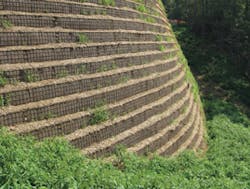
The face of the slope at this Alabama high school site included a wire form to aid construction, geogrid wrap,
and an erosion control blanket wrap to facilitate vegetation growth.
slope. Forestry worked with Tensar International-provider and engineer of the Sierra Slope Retention System and the Mesa Retaining Wall System used on the site-to propose a change in face angle of the slope from 45 degrees to 64 degrees, a move that would reduce the slope height by one-third and reduce overall project costs.
Technically speaking, a slope is defined as 69 degrees or less and is typically more economical than a retaining wall, which defined as 70 degrees or greater. The proposed change in slope angle substantially reduced the geogrid lengths and the required excavation, which reduced the overall project cost significantly.
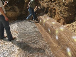
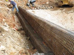
The Sierra Slope system, incorporates the use of high-density polypropylene (HDPE) Uniaxial Geogrids for primary reinforcement that internally reinforced the structure and fill materials. Uniaxial Geogrids carry large tensile loads applied in one direction, and their open aperture structure interlocks with natural fill materials, suiting them to mechanically stabilized earth and reinforced soil slope applications. The face of the slope incorporated a wire form to aid in construction and included a Tensar Biaxial (BX) Geogrid wrap, which served as secondary reinforcement to ensure the surface stability of the slope structure. In addition, a North American Green erosion control blanket wrap was used to facilitate vegetation growth on the face. According to Tensar, the Sierra system typically costs 30% to 60% less than conventional concrete walls. The Mesa Retaining Wall System uses locking connectors designed to mechanically connect the Tensar Uniaxial Geogrid to the wall units. The connectors are also designed to provide a low-strain, end-bearing connection that is not dependent on friction for structural integrity, and allows walls to be built near vertical or with a five-eighths-of-an-inch setback.According to Joe Bailey of Tensar’s Grade Separation Solutions, one of the challenges during construction was the fact that the slopes had a large quantity of soft and hard limestone just underneath the soil surface in many locations, which could have required blasting and excavation to accommodate the required design geogrid lengths. Forestry hired Birmingham Engineering & Construction Consultants Inc. to observe the excavation and determine when or if the excavation hit competent rock. By doing this, Forestry was able to reduce geogrid lengths significantly in some areas, providing additional cost savings for the project.
Supporting Temporary Bridge Bypasses
Permanent structures are not the only appropriate use for geosynthetic materials. One case in point is that of the temporary bridge bypasses the Wisconsin Department of Transportation recently had constructed while three bridge units across the Mississippi River were being replaced on Highway 25 between Nelson, WI, and Wabasha, MN. From summer 2009 to fall 2010, McCabe Construction of Eau Claire, WI, constructed bypasses supporting temporary bridges for access across the river’s backwaters, while Lunda Construction of Black River Falls, WI, constructed new permanent bridge units. Because the site is located next to a national wildlife refuge, the construction team had to ensure that the bypasses retained their structural integrity amid traffic loading and potential erosion from the backwaters.
A key structural element of the bypass was 95,000 square yards of geotextile fabric that stabilized the marsh bed, aggregate used as bypass road subgrade, and riprap used to backfill the edges of the bypass fill. Soils & Engineering Services Inc. of Madison, WI, a geotechnical and environmental consulting firm hired by the project engineer-Cedar Corp. of Menomonie, WI-recommended the use of a unique geotextile product for stabilizing the site. McCabe installed three different types of fabric manufactured by Propex and Belton Industries and supplied by Geo-Synthetics of Waukesha, WI.
First, Belton 1853 marsh-stabilization (MS) fabric was deployed onto the marsh bed and coarse aggregate was placed onto the fabric. On this project, the specified minimum tensile strength was 420-pounds-per-square-inch machine and cross direction, and the MS fabric was well within spec, according to Brady Shepler, vice president for McCabe, who added that the contractor had never worked with fabric that heavy-duty. Next, Geotex 701 subgrade aggregate separation fabric was set down. Roughly 120,000 cubic yards of dirt fill were then placed onto the second layer of fabric by dump trucks and dozers; this layer served as a base for the bypass road subgrade coarse aggregate. Geotex 1201 heavy riprap fabric was placed along the edges of the bypasses to stabilize riprap that prevented scouring.
The Geotex needle-punched nonwoven geotextile material features an unusual structure designed for integrity, superior filtration, and hydraulic conductivity. Polypropylene filaments are laid into a web and then are passed through thousands of needles that penetrate and orient the fibers, locking them together. This process is designed to impart versatility to the fabrics, which are available in many weights for varying strength requirements.
Due to the sensitive ecological nature of the site, installation was a challenge. Six areas required fabric with an average size of 750 feet long by 85 feet wide for a total of about 7,300 square yards per area. There was very little room for field fabrication, so Geo-Synthetics offered to construct the panels in its facility and have them shipped to the site. A “J” seam was specified whereby the panels were doubled up and had their edges folded over for stitching. Loops were also fabricated into the outer edges of the combined panels for the insertion of 8-inch high-density polyethylene pipe.
Once the panels were shipped to the site, they were lowered onto the water surface by an excavator while a pontoon boat and four-wheel all-terrain vehicle equipped with a winch spread them across the surface. The PVC pipe sections allowed uniform pulling and staking of the panel edges. “The thing that saved us on the job was that the product floated,” Shepler notes. “It was heavy to pull out, but the fact that it floated onto the water made installation much easier.” The average depth of the water was 7 feet, and conditions for deploying the fabric varied. “When there was vegetation sticking out of the water, it made installation difficult,” Shepler says. “If it was standing water, it was a piece of cake, but if there was current and vegetation, it took a lot of effort to get these panels into place.”
By December 2010, the last of the new bridge units reopened. Troy Peterson, project engineer for Cedar Corp., points out that the fabric served a key role in both the construction process and environmental protection.
“It was a good application, considering the fact that it was an environmentally sensitive area,” he says. “The fabric performed two functions. Number one, it supported the temporary road core. In addition to that, when they went to remove the bypasses, it acted as a barrier, a difference between the native material and the road core that was brought in. So when they came in to remove virtually all of the material that was brought in, they restored the area to the condition it was in before.”
Sealing a Landfill in a Seismic Zone
It’s a given that geosynthetic fabrics are used to stabilize environmentally sensitive areas. But landfill closures are particularly sensitive because their products are potentially hazardous. Their leachates can find their way into groundwater, and methane gas is a threat to air quality and becomes more of an explosion risk when released rapidly and in large quantities. A landfill such as the 66-acre Crazy Horse Canyon Landfill near Salinas, CA, has another challenge because it is located in a seismically active area that can rupture the landfill’s final cover and expose contaminants to air and groundwater. Subtitle D final cover is sufficient under normal circumstances, but Crazy Horse required something more when it closed in February 2009.
The initial cover design for closing this landfill was what Chris Richgels, P.E., senior engineer with Golder Associates in Roseville, CA, describes as a standard Subtitle D final cover involving the use of soil above a geomembrane, which is normally hydroseeded or planted with vegetation. But, he says, “the problem with the location of Crazy Horse is that it’s about 4 miles from the San Andreas Fault, so it’s in an area of high seismicity. The stability of the top vegetative soil was an issue.”
During the closure design phase, Richgels was approached by Agru America, provider of ClosureTurf, a 100% recyclable product designed for landfills and manufactured by ClosureTurf LLC. Agru America presented the material as an alternative to a soil layer and also provided testing data on the effectiveness of the material as a cover. Richgels says the research was convincing from an engineering standpoint.
The ClosureTurf system combines a drainage system and a geomembrane barrier that provides dimensional stability with a UV-resistant synthetic turf. The system is designed to allow for faster capping of the landfill to reduce odors, improve gas collection efficiency, and enhance compliance with Title V air-quality rules. The system is specifically designed for landfills in sensitive areas where soil erosion and sedimentation are major concerns. It is designed to eliminate soil loss and soil stability problems so that steeper waste slopes can be used. A sand infill ballast system is designed to keep the cover in place, even amid hurricane-force winds. The sand infill, combined with the transmission of the Super Gripnet lining, is designed to handle 4 inches of rain per hour without erosion. The synthetic grass also works as a grid that “locks” the sand in place if water quantity exceeds the drainage layer’s allowable flow of 4 inches per hour. Instead of anchoring, the system uses a high friction coefficient and ballast created by the sand infill.
According to Richgels, the design of the system reduced the extra drainage features that otherwise would have had to be added. “Typically, when you’re dealing with carrying concentrated water flow off of a final cover design, you’re using things like oversized drain culverts, catch basins, riprap [energy] dissipaters, that kind of thing,” he points out. “In another round of testing the manufacturer did, they used this product in drainage chutes and added a sand-cement ballast to the artificial turf layer. When we went through that design process and found out that it held up very well to the erosive forces of concentrated flow, even on slopes as steep as 3:1, we replaced all of the oversized drainage culverts and catch basins with this product and drainage chutes.”
In regard to cover, the original design would have used Super Gripnet beneath a vegetative soil layer. The vegetative soil layer was ultimately replaced by the ClosureTurf product, which eliminated the need for oversized drain culverts. The final cover design met the design basis of a 100-year, 24-hour storm event for a municipal solid waste landfill.
Installation of the final cover has been somewhat challenging, according to Richgels. Construction is scheduled in two phases. Phase 1, which consists of the topdeck area and much of the drainage infrastructure for that area, started in July 2011. Phase 2, which covers slopes on one end of the landfill as well as an asphalt parking lot area, will start in the spring and be completed in summer 2012.
“There are side slopes and other parts of the landfill that were going to be really difficult for earthworks to be performed-hauling soil in scrapers and dozers and what have you,” Richgels says. “It would have been really difficult if we had used the vegetative soil layer on top of the membrane. Using this product, those issues are still there, but they’re not nearly as big. If we had hauled in the vegetative soil layer, that was well over 200,000 yards of dirt. The site where the material was going to be hauled from was 30 miles away. By our estimate, that would have involved more than 600,000 diesel truck miles with a hauling cost of about $12 a cubic yard. So that was a substantial savings right there-about $2.4 million a year was avoided for soil hauling, not to mention the greenhouse gas emissions.” By comparison, the ClosureTurf system requires hauling in a few thousand tons of sand, Richgels reports.
“The biggest lesson that I personally learned on this project was learning ways to unthink the ways that we normally close landfills,” Richgels reflects. “When you think final closure, you immediately get it in your head, OK, we’re talking about oversized drainpipes, catch basins, catch basins on benches, and so forth. The [ClosureTurf] material, I think, is more or less like placing a skin on top of the landfill. You have to unlearn a lot of standard approaches that are normally taken.”


