Retained materials, whether they’re rock, soil, or stormwater, always have a tendency to move forward and downward with gravity. Holding them back calls for all the ingenuity at engineers’ disposal.
Concrete fabricated to form articulated concrete blocks (ACBs) and joined together into mats can help prevent erosion from runoff. They’re often used with a geotextile that separates the backfill or base layer from the topsoil. Concrete blocks, usually in a locking shape or with a locking device, connect to form segmental retaining walls (SRWs). Reinforced with a geotextile, they hold back soil and rock. Both ACBs and SRWs can withstand the pressure of gravity, not only more economically and easily than traditional methods, but also with a smaller footprint.
Uses of ACBs and SRWs include residential, such as the first case study below, involving a cliff face on Lake Erie; public, such as the Lake Royal auxiliary spillway and training dikes in Virginia; and commercial, such as the infilled canyon in San Antonio, TX.
Lake Erie, OH
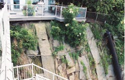
Some homeowners living on a bluff above Lake Erie in Ohio demolished their cottages and built new ones farther back from the eroding, nearly vertical 40-foot cliffs. Some residents had already lost their homes. Greg Norton’s father and his wife were determined to hang onto theirs.
“It’s an older cottage they’ve added on to, with a spectacular view of the lake,” Norton says. “Because of the erosion, it now sits about 15 feet away from the cliff.” The deck, which ties into the house, was even closer: The cliff was starting to erode under the posts.
Norton, owner of Norton Construction Services in Brunswick, OH, specializes in renovations and additions, especially custom work. He began working with Christopher Andrassy, who owns Andrassy Engineering Ltd. in Bay Village and specializes in designing erosion control and lake access structures on the lake.
First, Andrassy designed a stone breakwater. Two years later he added a cast-in-place reinforced concrete seawall behind it, which rises about half way up the cliff from a paved subfloor. In 2008, five years after the completion of the seawall, he designed a three-tiered retaining wall that reaches from the concrete wall to the top of the cliff, as well as a reinforced shotcrete wall to stabilize the cliff on the east side of the property. The owner chose the Versa-Lok Retaining Wall System for its appearance, and Andrassy used several types of Versa-Grid, designed to be used with it.
The face of the cliff is about 40 feet high and 65 feet wide, Andrassy says. The shale at the bottom transitions to glacial till, a heterogeneous mix of shales and clays. The upper 6 to 8 feet are clay soil mixed with some sand. The cliff erodes roughly 1 to 1.5 inches per year because of weathering, not primarily because of unstable soils.
Andrassy designed the stone breakwater, which is approximately 25 feet from the cliff, in 2000, and Norton Construction installed it in 2001. First, the Nortons hired “Wild Bill,” who has a specially designed front-end loader he drives into the lake, sometimes with water up to his chest, Norton says. “He dredged the area and stacked armor stones that weighed between 2 and 5 tons apiece. Riprap and seaweed fill the spaces between them.”
bottom and the sides of the auxiliary spillway
Norton excavated the area between the breakwater and the cliffs to bedrock, about 10 feet down. He used a pump to suck out mud and water and threw the loose stones over the armor stones. Then he poured a 1.5-foot thick subfloor between the breakwater and the cliffs to support the new retaining wall.
In 2002, Andrassy designed the 2-foot-thick concrete seawall behind a stair system that was already in place. It extends from the bedrock bottom behind the breakwater to halfway up the cliff. Norton Construction began by pouring the concrete in horizontal sections behind and against the breakwater. As each section was poured, crews backfilled between the wall and the cliff with 1- to 1.5-inch angular limestone from a nearby quarry.
“All the concrete was pumped over the 40-foot cliff,” Norton says. It ran through a 4-inch pipe along the side of the house and down the cliff. To move the blocks, crews set up a conveyor belt to send them down the cliff one at a time. The work was completed in 2003.
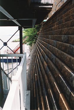
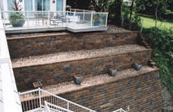
Then, in 2008, Andrassy designed the Versa-Lok retaining wall, which Norton completed in 2009. This wall is about 27 feet high and terminates at the face of the deck that was already there, Andrassy says. The lower tier, which sits on the seawall, is 18 feet high and reinforced with Versa-Grid VG 8.0, the middle tier is 4 feet high and reinforced with Versa-Grid VG 5.0, and the top tier is 5 feet high and reinforced with Versa-Grid VG 3.0. Each tier is stepped back to follow the natural face of the cliff. The geogrid is sandwiched between the layers of blocks, which are connected with Versa-Tuff pins, as well as wrapped around steel tubes that are bolted to the anchors.
Stepping the wall back has two advantages, Andrassy explains. “First, as you move back, you reduce the amount of backfill and the length of the geogrid. And second, the foundations of the upper tiers are on the notched cliff face, not on backfill that could settle a little.” Although this is more or less a vertical face, and pressure on the wall does build up with the height, the cliff is relatively solid. The pressure is primarily due to the backfill and there wasn’t much concern about settlement. Because of the tiers, the thickest sections are only about 3 feet, and most sections are just a couple of feet thick.
He found that the biggest challenge was the anchorage. “It was a fairly unique design for me,” he says. “The soil type is important in figuring out how to anchor the wall. The key is the bond that develops between the grout and the in situ soils or rock. It’s important to have an anchor long enough in each type of soil stratum to get sufficient anchorage.”
He researched the literature and made a conservative estimate about the levels of bond he could expect for grouted anchors in the various soils of the bluff. He specified one length of anchor at the
The blocks were stepped to follow the shape of the cliff.
bottom of the cliff face, because anchors bond easily to rock, and longer ones for the glacial till in the middle and in the soils at the top. It’s also important to allow enough time for the grout to adhere to the soil or rock. Test some anchors with a hydraulic ram when they’re in the wall and grouted, but before they’re connected to the wall, to see if the bond holds, he advises.
Perforated pipes on the back and bottom of each tier, and two in the biggest tier, provide drainage. Water drains at outlets at the sides.
On the west end of property line, a boathouse of concrete or masonry at the base of the cliff ties into the seawall pad and has been acting as a retaining wall for years, Andrassy says. Material has built up and over it, and it’s “quasi-stable.”
On the east end of the property, there’s a gap of about 6 feet between the seawall and the property line. “You’re not allowed to have a hardened wall against a property line because waves could create localized erosion in the corners,” Andrassy says. “But there is a big monolith of cast concrete on top of the stone that does go to property line, then steps back a little.” When the reinforced shotcrete wall is built, it will stabilize the cliff on the west side of the property.
Royal Lake Spillway Rehabilitation Project
“In 1977, when Royal Lake was built, it was fairly innovative,” says Donald J. Rissmeyer, an associate with A. Morton Thomas & Associates Inc. (AMT) in Richmond, VA. “But regulations are more stringent now, and more people live downstream.”
The lake was built as part of a Natural Resources Conservation Service (NRCS) watershed improvement project in Fairfax County, VA, that included six flood-control dams to protect homes, businesses, and infrastructure downstream. The lake stores floodwater during storm events and gradually releases it through a principal spillway, which regulates the water level behind the dam. Excess water flows through an auxiliary spillway, a grassy area bordered by earthen training dams.
Because of the state’s predominantly clay soils, there was potential for erosion in the spillway, which created a risk of dam failure. The area, a suburb of Washington, DC, had grown, and there were homes, businesses, two major highways, and two railroad lines, as well as bridges and utility lines, in the flood inundation zone downstream. Townhouses were built after the spillway in the spillway’s path.
To protect the downstream areas from flooding, Rissmeyer increased the capacity of the spillway to contain the probable maximum flood discharge from the lake by both widening it and raising the
training dikes on both sides. He also realigned and lengthened the spillway to direct water away from the townhouses.
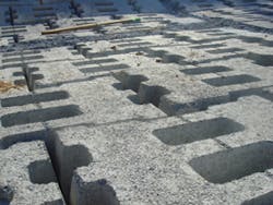
To protect the spillway and the dam from erosion, he used UltraFlex, an open-cell ACB mat system from Submar. Like other open cell ACBs, these blocks provide structural stability and have a large void ratio, which maximizes permeability and vegetative growth. But they’re also tapered from front to back, which is critical for spillway protection.
His design won an Honor Award in the 2009-2010 ACEC (American Council of Engineering Companies)/VA Engineering Excellence Awards. “One of the highlights was the fact that the restoration was hidden from view and environmentally sensitive,” he says.
The watershed consists of almost 24,000 acres of gently sloping land. It receives about 42 inches of rain per year. Stormwater flows from the spillway to Rabbit Branch Creek, then into Pohick Creek to Potomac River at Pohick Bay, which is part of Chesapeake Bay.
AMT provided design, bidding, and construction phase services for the spillway and the training dikes, including 1.8 acres of articulated concrete block matting. The company worked closely with the county and NRCS, the project sponsor, which provided a large amount of technical expertise, he says. Submar Inc., of Houma, LA, served as the subcontractor to Angler Environmental of Manassas, VA.
“Everybody helped,” Rissmeyer says. “We were just one player.”
A secondary purpose of the project was to improve water quality, although the quality in the area is quite good because the surrounding open space traps much of the sediment before it reaches Royal
Lake.
One challenge was the concern of the nearby residents. “Fairfax County has a very astute public, and this was right under the spotlight,” he says. In fact, he notes, “It’s the kind of project that’s usually frowned on, but it was necessary.”
The project was very sensitive to the environment. First, Submar’s system blends in seamlessly with the landscape. The project also used strict erosion control measures and observed a 20-foot buffer between the work site and Rabbit Branch Creek with adjacent wetlands during construction. Trees that had to be removed because of the realignment were replaced at a 1:1 ratio in areas outside the spillway footprint using reforestation techniques. Fairfax County Park Authority volunteers also moved native plants to safe areas. The trail system within the park was improved within the project footprint to improve accessibility.
An archaeology investigation revealed 37 flakes of quartz initially and three projectile points on closer investigation at what is believed to have been an Indian campsite in the woods near the banks of Rabbit Branch. The artifacts are now in the county archives.
Angler Environmental began excavating the spillway in August 2008. Crews widened it by 15 feet across and began raising the earthen training dikes on both sides with a maximum of a 2.5:1 slope.
“On Saturday, September 6, Tropical Storm Hanna hit,” Rissmeyer says. “It was absolutely the worst time.”
County emergency services and the contractor fought the flood, averting what could have been a disaster. “The county learned to have an emergency action plan on future projects,” he says. “Now specs are written for the contractor to be available at all times, and future projects are scheduled to finish before hurricane season.”
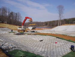
It took two weeks to repair the damage. Then crews backfilled the area with 4 inches of number 57 open-graded aggregate and covered it with Miramesh GR, a very flexible woven mesh geofabric, which the contractor chose.
The geofabric selection is important, Rissmeyer says. It has to serve the purpose of the project, work well with the blocks, and be adapted to the site. Miramesh GR retains the underlying aggregate and has apertures that are large enough to allow water, but not soil, to flow through. The project also has to be designed with enough detail that the manufacturer knows what to deliver and the contractor knows what to build.
The contractor also chose the UltraFlex block system. Each block is approximately 4 inches thick in the front and 5 inches thick in the back. This tapering is critical for spillway protection so the edge isn’t exposed to the flow of water, he says. If even one block is exposed to the flood forces, the whole mat can fail.
The tiered walls extend like wings at acute angles from the main wall, each divided into increasingly lower and longer walls.
“I hadn’t worked with UltraFlex before,” Rissmeyer says. “It’s definitely a highly engineered system. The details matter.” The blocks need to be stepped in the right direction, and for that, there has to be a mat-layout plan so the contractor knows exactly where to place each one.
Once the mats were in place, crews backfilled the cells with sand to separate the geofabric from the topsoil, made one pass with a roller on top, then covered the entire mat with 6 inches of a soil and peat moss mixture. “One of the concerns was that the vegetative cover needs to be maintained,” he says. “With the blocks below the root zone, the vegetation could dry out. We used more topsoil than normal to retain moisture and to make sure the entire root zone was mostly out of the blocks.”
The site was seeded with drought-resistant native grasses. Maintenance includes mowing the vegetation to keep it at 4 to 6 inches high, inspecting it for erosion, and reseeding or replanting if necessary.
The project was finished in March 2009.
“It was a success,” he says. “These mats seem to work really well when they’re designed and installed correctly.”
San Antonio, TX
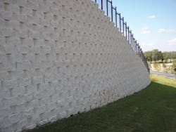
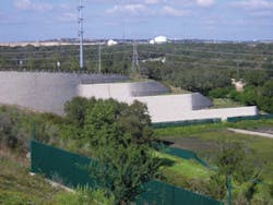
In San Antonio, TX, with its rolling hills and limestone bluffs, a sleek white retaining wall echoes the walls of nearby canyons. Rising 45 feet above the original grade, it supports the main entry drive of the new corporate headquarters for Tesoro Corp., an independent refiner and marketer of petroleum products. Three tiers break up the stark wall face and extend like great white wings, enclosing grassy terraces.
It’s only with advances in retaining wall technology and design that the project was possible at all. The campus sits on what had been a steep canyon that was filled in as the retaining wall was built, says Richard Jenkins, owner of Ettamar Inc. in Round Rock, TX, who designed the structural components of the wall as well as the drainage. The biggest challenge was selecting a wall to support the roadway and the adjacent pad behind it.
“It has a significant differential grade,” Jenkins says. “There aren’t a lot of options when you get to 45 feet in height. A reinforced concrete wall would have been so thick at the base, it would have been far too massive to consider building.” Instead, he chose a mechanically stabilized, earth-segmental retaining wall, which supports the elevation without taking up the space of a concrete wall. “These walls really allow site developers to develop sites they wouldn’t have been able to build before.”
He specified Keystone Retaining Wall Systems’ Compac II blocks as well as three tensile strengths of Mirafi uniaxial woven polyester geotextiles, 3XT, 5XT, and 8XT.
The project was designed in 2006 and built in 2007. It used 18,000 square feet of Keystone blocks.
The retaining wall is essentially one gracefully curved wall. At its highest elevation it is 45 feet high. Lower tiers arch away from this main wall like the veins of a leaf. Each of these tiers is divided into three increasingly lower and longer walls, each of which forms a terrace.
The three tiers were a challenge. Although they’re an aesthetic feature, they had serious structural implications, Jenkins says, because multiple structures in close proximity import a load on each other, and engineers have to analyze the surcharges and the interplay between them.
“What you’re looking for is the relationship between the upper and lower wall, how far apart they are and their respective heights. Then you can understand how the upper wall will load the lower wall, and you can reinforce the lower wall so it isn’t only stable for its own load, but it can also support the load from the upper wall. When three walls are involved, it’s even more complicated. It’s important to understand the interplay between all three of them.”
According to Keystone, the base layer of these walls should be installed below grade. This locks the wall in place and also helps prevent erosion and scouring at the base of the wall. Once each layer is installed, it’s important to fill all the voids in and between the units as well as 2 feet behind the wall with well-draining fill and to compact it to eliminate settling. Fiberglass pins are inserted into slots in the units, the geogrid is hooked over the pins, and the next row of blocks is installed.
The key to the strength of SRWs is the tensile strength of the geogrid, Jenkins says. Once the wall system is connected, the mass is too large to be moved by the unstable soil behind it. He specified Miragrid 8XT, which has the highest tensile strength, for the bottom tier, 5XT for the middle tier, and 3XT for the top.
The tiers split off from the main wall at acute angles, which was another challenge. The joint has to be detailed properly, and the reinforcing materials cannot be settlement prone. The contractor, Cribley Enterprises Inc. of San Antonio, used 2-inch, clean, free-draining backfill, with a pH between 3.0 and 9.0.
“Some geogrids are affected negatively by soil chemistry,” Jenkins says. “If the pH is too extreme, the design could be affected. We were very fortunate that the project is located in a part of San Antonio that’s very rocky. We had good crushed stone available close by. It made the design much more straightforward.”
For drainage, 4-inch diameter perforated ADS drainpipe was used, prewrapped with ADS filter fabric. The underlying soils have some clay, and rainfall is uneven, he says. San Antonio just came through a 5-year drought and is now experiencing above average rainfall. A drainage system onsite keeps stormwater runoff away from the wall.
Because the canyon was being filled in behind the wall, Cribley Enterprises used the existing soils as backfill. Although this was convenient, it also posed a daunting challenge, because the two major operations had to take place simultaneously.
“James Stipe [the project manager for Cribley Enterprises had a much more complex task than the structural design,” Jenkins says. “Imagine a canyon being filled in with large earth movers and your retaining wall has to be built in sync with them and on schedule.” The wall building can’t get too far ahead, or there will be nothing to work on. But the fill can’t get too far ahead, either, or there will be no wall it to support it. Cribley Enterprises’ experience in projects of this nature was instrumental, he says, as well as the cooperation among all those involved.
“On a project this complex, it’s hard to get everyone together and on the same page. You have to have good communication. On this project, everyone understood exactly what roles and responsibility they had. Everyone’s availability to coordinate this thing as well as they did made it a very successful project. We really enjoyed being part of it.”
