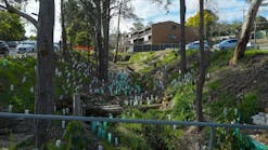
Construction projects that are meant to last for years, such as those involving public roads and large dams, require stability. That stability is essential for both public safety and cost-effectiveness. Retaining walls are a common element in these major projects.
Cove Lane Interchange
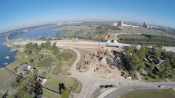
The Cove Lane Interchange is a major transportation project built for the Louisiana Department of Transportation and Development (DOTD). It is located near the city of Lake Charles in Calcasieu Parish, LA.
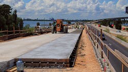
This $38.6 million DOTD project included a full interchange at Cove Lane and Interstate 210, a traffic roundabout on Cove Lane, and an extension of Cove Lane north to connect with a new public roadway. The new interchange raised the level of I-210 and allowed the new road to run beneath it.
The new state road was needed to handle traffic to two large resort and casino attractions. That easier access would relieve traffic congestion and increase visitor numbers to these attractions and thus be a boost for the local economy.
This DOTD project covered 1.8 miles. It was the first of three phases of work to relieve traffic congestion along I-210, which is a major interstate artery in southern Louisiana.
The project was complex. Retaining walls, carefully designed and constructed, were an essential part of its success. The walls included were from Keystone Retaining Wall Systems.
Johnson Brothers Construction served as contractor for the retaining wall components of the project. Civil engineering was done by Stantec. Geotechnical engineering was provided by GeoEngineers Inc. of Baton Rouge, LA, and elsewhere.
The project began with subsurface exploration and testing covering 11,200 linear feet. This work was done between August and October 2012. The majority of construction activities occurred between November 2013 and April 2015.
This innovative project was fast-tracked from the beginning. The transportation improvements had to be finished before the new Golden Nugget casino could receive its operating license from the Louisiana Gaming Commission.
“The existing casino traffic was already a strain on the interchange. Community leaders were looking at [improving traffic flow for] additional economic development, too,” says Ivy Harmon, geotechnical engineer with GeoEngineers Inc. “We worked for the owners of the casino, AmeriStar, because state funding couldn’t come online fast enough.”
“The gaming license controlled and created our work schedule,” says Larry Sant, associate and senior geotechnical engineer with GeoEngineers.
The Cove Lane Interchange project came with a number of major challenges and problems that had to be solved for its success. The first consideration was the soils in the area, and the fast-track requirement was of immediate impact here.
“Geotechnical exploration was very much accelerated,” says Harmon. “We had five drill rigs going at the same time, and then accelerated lab testing and accelerated design [to facilitate] quick construction.”
“Within one week of the state signing the contract, we were out there with five rigs already drilling,” says Sant.
The poor quality of the soils in the area required extensive testing, really a geotechnical investigation that included 128 explorations (43 drilled soil borings and 85 cone penetration tests [CPTs]) to depths of 20 to 120 feet. Samples collected from areas for the I-210 overpass structure with approach embankments and ramps were then tested in the laboratory.
The results revealed that soils ranged from over-consolidated Pleistocene clay to soft alluvial deposits. Pore spaces within clay soil hold water. When a load is added to that soil, it gets squeezed like a sponge, except that water does not move through clay very fast. This characteristic also influenced the work schedule.
“Every six weeks, we put on three more feet of fill and then let it settle for six weeks so the water could flow out and the soil could gain strength,” explains Sant. “That’s not unusual with our soft soils. The problem is that sometimes settlement occurs, but there is a nearby area that doesn’t settle or settle at the same rate, like an adjacent pile-supported bridge abutment.”
Adding too much fill at once could cause subgrade soil failure. For example, one test area near a ditch would support a lift of 1 to 2 feet, but when 4 feet of fill was added, the small test section failed, causing a mud wave.
The soft soils are plenty challenging for complex projects such as this one. Sant says that on this site the soils often varied even within very small areas. One example was relatively strong ground where trees were growing adjacent to a relatively weak swamp near the canal.
Extra support was needed to ensure long-term stability of load-bearing walls in some areas, such as the approach sections. Timber piles—more than 8,000—were driven into the ground below a constructed concrete load transfer slab. (Larger 24-inch prestressed concrete piles were installed to support the I-210 bridge abutments.)
The GeoEngineers team used Pile Driving Analyzer (PDA) equipment to evaluate and monitor installation of one in every 50 pilings placed for acceptance of the more than 8,000 driven piles. The data collected proved useful to DOTD for future projects.
“We were required to test two percent of those pilings. We had five rigs going at once. The vast majority of the pilings drove in beautifully,” recalls Sant.
Space limitations posed another challenge. Harmon explains that the project was not only a matter of figuring out how to get the work done on time, but also how to fit the structures into the space available.
“We needed it to be partially above grade and partially at grade level. The design we used for the interchange was a tight urban diamond,” she explains.
“We had to leave a limited footprint on the area. To the south there is a park, a beach, and a neighborhood. The canal runs east and west, just north of the intersection. Normally there could be slopes for approach fill, but not with our soils and the need for flood protection,” says Sant.
Another challenge was that traffic had to be kept moving on this major transportation artery throughout construction, which had to be done in phases. To achieve that result efficiently and ensure the safety of workers, the cost and time of constructing temporary walls had to be factored in.
Given the terrain and site requirements, two different Keystone wall systems were used for specific areas. They had to be integrated properly to work together successfully. Time and budget constraints added to the challenges of the exacting work.
KeySteel has inextensible steel reinforcements. It was used for load-bearing wall sections of the bridge. KeyGrid has extensible geogrid reinforcement. It was used for all other approach walls. KeyGrid uses Keystone Compac II units and TenCate Miragrid geogrids made by TenCate Geosynthetics. Combining the two wall systems on the project ensured that the structural loads at the abutment had the best design for that portion.
5,000 square feet of KeySteel (KeySystem I) was installed on the bridge structure. The ramp and temporary walls received 127,000 square feet of KeyGrid (KeySystem II). 8,000 driven piles (88,000 linear pile feet) were driven to support a concrete slab under the bridge structure. The highest wall was 25 feet tall. Most were 10 to 15 feet in height.
The Cove Lane Interchange project required three distinct phases of construction. Each was scheduled as precisely as possible so as to not interfere with traffic and to get the work finished as quickly as possible.
During the first phase, walls 1, 2, and 3, which support the westbound ramp (using KeySystem II), were built, along with a smaller bridge abutment (also using KeySystem II) for the northbound Cove Lane bridge to the Golden Nugget Casino and the nearby golf course.
The second phase included construction of the approach and bridge abutment walls (4 and 5), as well as temporary walls that supported the eastbound lanes of I-210. Walls 6 and 7, which support the eastbound ramp, were also built then.
The third phase involved construction of walls 8 and 9 of the approach and bridge abutment. During this last phase, the height of portions of walls 1, 2, and 3 was increased to final finished-grade vertical alignment.
To help keep the project on schedule by shortening settlement time and to verify proper settlement for stability, the GeoEngineers team staged an 11-foot surcharge load with 60-foot wick drains from Hayward Baker on a soft portion of the project site. This was done where I-210 exited to the Cline Canal Bridge.
Weather can be a real problem for construction work in south Louisiana. Harmon says that the region “gets to experience hurricane season, so we always have that threat. We always have a plan if a hurricane ever hit—what equipment would be moved, what booms on cranes would be lowered, how we would proceed. Luckily, we didn’t have any major storms during this project.”
She continues, “We did experience a rare weather event. One of our shutdowns was because it snowed, enough to throw everybody into a state. The rigs were ice-covered. The vehicles were inaccessible. The ground was so muddy and wet we couldn’t work.”
To indicate how unusual the snowfall was, Sant adds, “We might have one day a year with overnight temperature below 32 degrees.”
Water and saturated ground are ever-present components of construction and engineering projects in the region. Harmon says, “We do a design based on water at the surface.”
Sant adds, “Dig a hole and it will fill with water. Everything runs off into canals and bays.” He says the average rainfall is 65 inches a year and comes in heavy downpours. “It can be a beautiful morning, but nearly every day it rains for an hour or two. Then the sun comes out for the rest of the day.”
As for wildlife at the project site, “Once the construction got going, there was so much noise that the wildlife cleared out,” says Harmon. But before the noise began, the engineers and other employees saw both wildlife and signs of their presence. “We did encounter two water moccasins,” recalls Harmon.
“I saw a few alligators once when we were building the embankment, and I saw gator footprints on the sand by equipment at the edge of the embankment,” says Sant. “The contractor mentioned seeing alligators, too.”
GeoEngineers brought employees from the company’s northwest offices in Portland and Seattle to help on this large and unusual project. “As part of their orientation, they were told which wildlife you would expect to see onsite. In their home locations, they might be watching for bears, but here it would be snakes and alligators,” notes Sant.
The Cove Lane Interchange project won the Engineering News Record Award of Merit, TX, and Louisiana Best Projects of 2016.
Stampede Dam
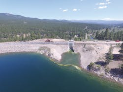
Completed in 1970 as part of the Washoe Project, California’s Stampede Dam is situated on the Little Truckee River, about 10 miles northeast of Truckee, CA. The location is within the Sierra Nevada Mountains.
The dam’s lake is a major area attraction for boating and other recreational activities. It also supplies water for fishery operations, particularly for the endangered cui-ui.
The Stampede Dam is owned and operated by the Bureau of Reclamation. This division of the US Department of the Interior manages water resources and operations in the western part of the country.
Stampede Dam was constructed of rock-filled rolled earth. Its original height was 239 feet and its length is still 1,511 feet. When built, this dam could store 226,500 acre-feet of water.
“Every four years, we relook at the risk [of failure] and condition of each dam with a team of new people,” explains Scott Schoenfeld, acting office manager for the Bureau’s Lahontan Basin Area office in Carson City, NV. “We ask ourselves, ‘How would we want to build this dam if we were building it today?’ If there is a significant change from how we built it, we fix the older dam. Our knowledge changes. We are always learning more about dam safety.”
When this reassessment of the Stampede Dam was done, it was found to be structurally safe in terms of earthquake risk. Heavy rainstorms, however, posed a significant risk of major flooding.
Since Stampede Dam was constructed, the areas around it and downstream, including the city of Reno, NV, have increased in population. More people were being put at risk, along with property and tourism as a significant part of the local economy.
Schoenfeld says that the Bureau of Reclamation’s evaluating engineers saw catastrophic possibilities. If a significant storm that resulted in flooding caused Stampede Dam to overflow its banks, the earthen Boca Dam (built 6 miles downstream in 1936) would also be at risk of overtopping and failure.
Kyle Hughes in the Bureau’s Shasta Lake, CA, office, construction engineer for the project, says that the purpose of raising the crest of Stampede Dam was “to be able to retain very extreme floods. If a huge flood happens, we want the capacity to retain it.”
Raising the height of Stampede Dam by about 11.5 feet would give the dam the capacity to store almost 141 million cubic feet more of water. The project became part of the Bureau of Reclamation’s ongoing Safety of Dams Modification Project.
The cost of the project was $21.8 million. NW Construction Inc. of Bozeman, MT, served as contractor.
Work on raising the crest of Stampede Dam started in September 2016. The project was finished in October 2018. Two years were required and scheduled for construction because the heavy snowfalls in the area make winter work impossible.
“We had two winter shutdowns, from November to April each year, which were planned,” says Hughes.
He adds, “We had an unusually wet winter during 2016 to 2017. There were certain work items we had to get completed in April [so as to be ready for work during the next season of good weather]. So we had to plow seven miles of county road, one lane, that had six to seven feet of snow, just to get the construction people out there. If we hadn’t done that, the project could have faced a one-year delay.”
Another challenge: “The area around Stampede Dam is highly recreational. We were trying to work in a safe and respectful way toward the public. It took a period for the general public to get used to the changes, such as the public road over the dam being closed, and we were using one of the campgrounds,” says Hughes.
Crew size ranged from a high of about 50 people to as few as 10. The average number of workers was about 20.
Wildlife did not pose any problem on this project. “We had to do some bald eagle monitoring, but that was planned, to make sure we weren’t disturbing them,” says Hughes.
Each lift of infill material was about a foot high. It was reinforced with Reinforced Earth Co.’s galvanized steel strips and then compacted down before another lift of infill was added.
“The backfill we used was all local material,” says Hughes. “Without having to import material from somewhere else, we saved money.”
The Reinforced Earth MSE walls totaled about 100,000 square feet. They were arranged in a predominantly 30-foot-wide back-to-back configuration, along a crest center line that stretched for about three-fourths of a mile. Wall height usually reached 16 feet, but was over 18 feet in a few sections. Standard traffic surcharge loading was done for the raised roadway that was built atop and between the walls.
The Stampede Dam project is the second time the Bureau of Reclamation has used a mechanically stabilized earth wall from the Reinforced Earth Co. to raise the height of one of its dams. In 1982, the agency raised the height of the Lake Sherburne Dam in Babb, MT, this way.
“It’s an innovative approach to raising a traditional earthen bank dam. It’s more cost-effective than the traditional approach, because you don’t have to increase the slopes on each side to keep the increased height stable,” explains Hughes.
Summing up the Stampede Dam project, he says, “We didn’t have any design or site construction problems. We had a great team from the Bureau of Reclamation. The supplier and designer of the mechanically stabilized wall, Reinforced Earth, did an outstanding job. They were very professional.”
Nashville Airport
Sometimes, in engineering projects, it’s better to start over. Instead of continuing to try to troubleshoot problems that a planned design is causing, go back to the drawing board—or the design software—and start over to find a different approach for the project.
That is exactly what happened with a retaining wall project at the John C. Tune Airport in Nashville, TN. The wall was needed to provide support for a new hangar for the plane used by the Governor of Tennessee.
The original plan for the project was to build a straightforward gravity retaining wall. Manufacturer and installer for the project was Redi-Rock of K.I.T. (Kentucky, Indiana, Tennessee) in Nashville. The site contractor was Civil Constructors LLC of Franklin, TN.
Excavation of 32 feet to start the wall—right up to the property line—revealed an unexpected problem. The contractor’s crew discovered that unstable fill material had been used on the adjacent property.
Now there was a problem with the crest slope of the wall. Blasting unearthed buried boulders instead of the expected solid rock, and the limestone rock cut wasn’t as tall as it was expected to be. It was obvious that the wall could not be built as planned. It was time to call in an expert.
Enter Clint Hines, principal with J.C. Hines & Associates in Cincinnati, OH. Hines specializes in designing retaining walls. He considered several options, including moving the wall and using a geogrid to stabilize it. “But we didn’t want to do that because it would limit space in front of the hangar,” he says.
The wall project was already taking longer and costing more than originally planned. But Hines knew it had to be taller (and more expensive) to make the crest slope stable and without using geogrid. That meant the wall’s base had to be wider to support its increased height.
Hines presented his final design for construction of the retaining wall in July 2018. The airport’s board approved it in October. Construction began that month and was finished a few weeks later.
“We had a lot of bad rain during the fall and a lot of water to deal with. We had to design a drain system at the bottom of the wall, blasting out rock to get the drain away from the wall,” he recalls.
The retaining wall for the hangar property at the airport required 979 blocks in the Ledgestone texture, for the look of randomly stacked stone. Of that number, 806 blocks are Redi-Rock’s XL. The rest, moving toward the top of the wall, are standard sizes.
Those Redi-Rock blocks were built into a wall that measures 10,214 square feet.
The wall is 429 feet long and stands 25.5 feet high at its maximum point.
Redi-Rock’s XL hollow-core blocks are produced in widths of 52, 72, and 96 inches. At 36 inches, they are twice the height of standard Redi-Rock blocks. XL blocks allow a retaining wall to be built taller, even when space is tight, while using less concrete.
“The XL blocks are so deep. They give you enough width at the bottom for good support,” says Hines. “The largest XL blocks are really wide. It’s hard to make an eight-foot-wide block that is lightweight enough to pick up and also structurally stable.”
Redi-Rock of K.I.T. had not installed the XL size blocks on a project as large as this one before. However, the crew of five used the same equipment they use for installing standard-size blocks: two skid-steers, a Caterpillar 314 Trackhoe with a fully hydraulic totem clamp, and a vibratory roller.
“We use Redi-Rock quite a bit, and Redi-Rock is a leader in the field with its custom software,” says Hines. “We use it on all of our jobs with Redi-Rock products.”
He notes that Redi-Rock paid Fine Software, a leading geotechnical software firm, to create a custom version of the software for designing retaining walls using Redi-Rock’s products. The software is called Redi-Rock Wall Professional.
The Redi-Rock software “helps you optimize the design. It tells you exactly how many courses up of the large blocks you must use before you can use the next smaller size. It’s so much easier and [more] accurate than trying to build a spreadsheet. They’re never as effective as deliberate finite-analysis software,” he says.
Knowing precisely when it is safe to change to the next smaller size of blocks means saving the customer money. It also allows for more exact bidding on jobs.
Along with the Redi-Rock software and the XL blocks, which make a taller wall easier to achieve, Hines credits accurate geotechnical modeling for the success of this project. Soil types and conditions varied a great deal at the location.
Testing led to accurate models that revealed what shear-strength parameters to use. This precise knowledge of where soil strata changed is essential when building tall wall projects like this one.
As for the XL blocks, Hines says that he has designed several projects using them since this airport project. These projects are awaiting construction.
