Retaining walls vary tremendously in design and setting, but they all share a functional purpose. A well-designed retaining wall can enhance the appearance of a site, but if it doesn’t stabilize the earth and last, it’s not a success. Retaining walls in the following projects add value to their sites and are serving their purpose.
The Parklands
About 3,800 acres of the last part of undeveloped land around Louisville, KY, has been turned into four interconnected public parks. The entire natural area, which is called The Parklands, forms a 21-mile-long corridor.
The Parklands was created by a Louisville nonprofit organization, 21st Century Parks. The group’s goal was to create a park system suitable for the 21st century while evoking the seminal Frederick Olmsted model that produced Central Park in New York City and many other major metropolitan parks across the US.
The unifying feature of The Parklands is Floyds Fork. This stream flows for 19 miles through all of the individual parks. Floyds Fork can be accessed at various points and offers fishing and paddling to visitors.
The four parks—Beckley Creek, Pope Lick, Turkey Run, and Broad Run, plus a linear corridor known as The Strand—are also connected by more than 100 miles of trails. The trail system is for hikers and bike riders. Bicyclists can also enjoy the 100-mile Louisville Loop. It connects The Parklands to other parks and recreational areas in Louisville.
A number of retaining walls were installed for different sections of The Parklands. Although these walls vary in height and purpose, it was essential that each wall look as natural as the entire park system does.
The project differed in atmosphere and appearance from a transportation or commercial project. Anything that looked artificial would stand out against the background of natural landscape. The walls had to match areas of natural stone and to look as though they had always been there.
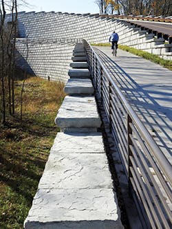
The Parklands section of the Louisville Loop includes a challenging switchback. At the outside of the curve stands an attractive gravity wall by the path where the riders race by. Made of Redi-Rock Ledgestone from Redi-Rock of Kentuckiana, the wall includes retaining wall blocks topped with freestanding blocks and caps.
Not far from this wall is another Redi-Rock wall in Beckley Creek Park. It stands beneath the overpass that was created for Interstate 64, the main highway from Louisville to Lexington and beyond to eastern Kentucky. This overpass was necessary to provide access throughout all of the park system. To keep the stone secure beneath the overpass, a 1,200-square-foot headwall was installed.
The first phase of retaining wall construction at The Parklands includes four Redi-Rock walls, adding up to more than 7,000 square feet. The tallest is 13.5 feet. It has an additional 60 inches of exposed freestanding blocks on top of the wall. These four walls were installed in only six weeks.
To reduce the cost of backfill materials and geogrid, gravity walls were installed whenever possible. Redi-Rock’s compatible design minimized appearance differences where reinforced wall sections met gravity sections.
The most dramatic Redi-Rock wall in The Parklands is 41 feet tall. It runs for about 500 sloping feet. Completed in January 2013, the wall rises above the lowlands of Floyds Fork and serves as a major connection between the northern and southern parks.
“The purpose of the wall was to get the new road connected to Distillery Bend and to separate vehicular traffic from bicyclists. It was more utilitarian than scenic,” says Clint Hines, president of the Cincinnati area engineering firm JC Hines & Associates.
This “great wall” has two tracks, which are mostly parallel. The road for cars that the wall supports is 22 feet wide. The adjoining track for bicyclists and hikers measures 12 feet wide. The road serves as an entrance and exit to Beckley Creek Park.
This tallest wall plus two other separate walls built at the same time total 21,000 square feet. The design of the wall was inspired by a bridge built of Indiana limestone in Louisville’s Tyler Park in 1904. The Tyler Park Bridge has become a known landmark in Louisville. It was probably designed by John Olmsted, the son of noted park designer Frederick Law Olmsted. The bridge has a large arch that allows pedestrians to walk from one side of Tyler Park to the other without having to cross a busy street.
Hines says the challenges to building the great wall and two adjoining walls were significant. “Not only was the wall very tall, but these walls were back-to-back. There wasn’t an opportunity to batten [set back] the walls, and there was a tunnel at one end. The walls had to meet precisely.”
He adds, “We were dealing with creek-bottom soils. They are prone to settling. We undercut those soils, replacing them with number 57 crushed stone wrapped with woven geotextile fabric from Mirafi.”
Areas beneath the great wall’s base often flood. Making the slope more gradual would have helped solve this problem, but there wasn’t enough land to do that.
Drainage pipes, 48 and 36 inches in diameter, were placed through the wall. Built-in slip joints extend to the top of the wall. These slip joints protect the wall from any damage due to settling.
“It’s much more difficult to align walls at slip joints. At the time, I thought [these precautions] were overkill, but there has been some three-eighths of an inch of settlement, even with the slip joints,” notes Hines.
Construction for this third phase of retaining walls at The Parklands began in November 2012. It was finished in early spring 2013 and took 22 actual work days.
Because the project received federal funding, engineers and designers had to meet various federal guidelines. One example was federal Americans With Disabilities Act guidelines for handicapped access, including a walking grade of no more than 5%. Another was moving the great wall’s original site so as not to intrude on a protected archaeological location.
Specifying architects for the entire project were Wallace Roberts & Todd and Bravura. Specifying engineers were HNTB Corporation and QK4 Inc.
Retaining wall engineers were Civil Design Professionals and JC Hines & Associates. Wall installation was done by MAC Construction and Excavating and Redi-Rock of Kentuckiana.
Underneath the sidewalk on the Seattle waterfront
Seattle’s Seawall
Built between 1916 and 1936, Seattle’s seawall was in bad shape. Timber supports had decayed. Continual exposure to wind and waves had caused damage, as did the 6.8 magnitude Nisqually earthquake in February 2001, which was felt over much of the Puget Sound region.
The old seawall was almost certainly not strong enough to withstand another major earthquake. If it fell, nearby property would be at risk for damage. And, of course, people could be hurt
or drowned.
Replacing the old deteriorating seawall made sense to officials at the Seattle Department of Transportation (SDOT). The project was made part of the larger effort to redevelop Seattle’s waterfront district.
The new Elliott Bay Seawall will cost about $410.2 million. It was funded mostly by a 30-year bond measure that voters approved in 2012.
Construction on the new seawall began in late 2013 and will be finished later this year. The seawall has three main parts: a cast-in-place support slab with custom precast concrete face panels, precast concrete Z-shaped superstructure segments, and precast sidewalk panels.
The Z forms “are a unique design, specifically for the seawall, to create the weight and structure necessary to hold up the panels,” says Lorelei Williams, director of Capital Projects and Roadway Structures for SDOT.
The new seawall will act as a retaining wall between Elliott Bay and the waterfront. It will replace 3,710 linear feet of the old seawall.
Oldcastle Precast of Auburn, WA, is the supplier of the precast superstructure segments and the seawall facade panels. The company has worked closely with Mortenson-Manson, the joint venture general contractor and construction manager.
The new seawall is supported by 400 of the precast concrete Z-shaped superstructure segments. Measuring 8 feet wide by 9 feet tall and extending 13 feet, they secure the seawall’s cantilevered sidewalk.
The precast concrete facade panels are 8 feet wide and 19 feet tall, with a thickness of 15 inches. They have various custom finishes.
Producing these precisely sized precast concrete components meant creating customized formwork. The process also required a large facility to handle the size and weight of the concrete structures. Taking the time to make that formwork made possible a same-time pour of all of the concrete. The casting was done indoors with self-consolidating concrete.
Besides replacing the old seawall with one strong enough to protect the waterfront from waves and tides and to withstand earthquakes, there was another reason to build a new wall: protection of a precious natural resource, salmon. Most of Seattle’s shoreline is covered by piers and buildings, which cast shadows on the water. Young salmon need light to find food and shelter and keep on their migratory routes. The part of the new seawall that will help the salmon and delight the tourists is the overhanging, light-penetrating sidewalk. The seawall was moved inward, and a custom precast sidewalk that contains embedded glass blocks was installed.
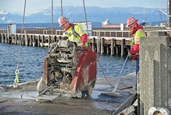
Removing a section of the old sidewalk
The blocks within the concrete are of very strong glass. They are safe for pedestrians and, on the reinforced driveways, can support delivery trucks and cars that are bound for ferries. This special sidewalk was manufactured by the Canadian firm Architectural Precast Structures.
Another assist for the salmon and other marine life comes from the three different textured finishes on the precast concrete facades. The various textures give tiny marine animals a surface they can hold onto. They include a geometric pattern with tide markings, a cobblestone-like pattern, and a pattern with different texture types.
“We’ll do a study for 10 years to see which surfaces are the most effective,” says Williams.
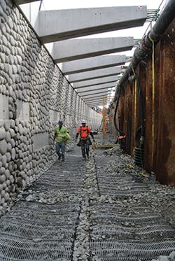
A bench-like structure was also installed to enhance the habitat for marine wildlife. It runs for 3,116 feet, paralleling the seawall. It varies in width from 10 to 13 feet.
“It’s mesh with rocks inside, a rock mattress. Adjacent to it are the facial panels of the seawall,” explains Williams.
Any large construction project comes with lots of challenges. That is true of the new seawall.
“We had a large hole 30 feet deep,” says Williams. “We had to dig down to the platform on top of the piers. [With this much disruption], the City made the decision that maintaining access to businesses there would have been too expensive. The City closed those businesses down for nine months and paid the owners the revenue they lost.”
Williams says that the original planning called for dewatering the site, but that proved to be impractical. Instead, the City used an environmentally friendly strategy of freezing the ground down to 35 feet, created by SoilFreeze, a Seattle firm.
The technique involves running salt brine through underground pipes to freeze the ground solid. Groundwater is stopped from moving as long as necessary for construction work. When construction is completed, the pipes are removed and the ground thaws. Because the ground doesn’t dry out as it would during dewatering, there is no risk of instability to buildings.
In planning the new seawall, SDOT officials took climate change and resulting sea level rise into consideration. They consulted with researchers at the nearby University of Washington’s (UW) Climate Impacts Group. This organization does research on climate science for communities across the western United States.
“We wanted to take into consideration what could be coming in the future, not only tidal, but seismic,” explains Williams. “We also worked with permitting agencies and UW for strategies to improve the habitat.”
Recommendations from the Climate Impacts Group on sea rise have become the city of Seattle’s standard reference points. In turn, the new seawall’s design and construction are a pilot in using the climate data for guidance.
The group’s predictions on future sea level rise in Elliott Bay range from a rise as little as 6 inches to as much as 50 inches. SDOT chose to key on the highest possible level.
Knowing that the new seawall will last at least 75 years, and erring on the side of caution with regard to sea level rise, officials planned the wall and the adjoining Alaskan Way to reduce the risk of tidal inundation during extreme high-water events.
An example of such an event would be a storm surge at high tide. But even if the highest predicted sea level rise were to occur, the current seawall elevation would be 3 feet above the new still water level.
Midway Middle School
Part of the Roane County Public School System, Midway Middle School is located in Ten Mile, TN. That’s about 55 miles southwest of Knoxville and 38 miles southwest of Oak Ridge, in the central part of the state.
Over several months, an existing wall behind the school—built only eight years earlier—began crumbling apart. So many rocks fell onto the road below that it had to be closed.
The deteriorating wall posed a safety hazard to students and anyone else in the vicinity. The closed road was a major transportation headache because the school buses that traveled it twice daily had to be rerouted.
It was neither cost effective nor wise to repair the wall. The obvious solution was to install a new wall, one that was not only durable but also attractive. School district officials opted for a Stone Strong precast concrete block wall.
Choosing precast concrete meant that the wall would be finished much sooner than a poured concrete wall. Precast eliminates the need to wait for the curing times before backfilling.
Speed of installation was essential because the wall had to be completely finished before the start of the 2014–2015 school year. All of the planning, design, and construction work had to be done between May and August 2014.
“One of the biggest reasons we went with this gravity-type system was because of property acquisition issues. There was a limited amount of space between the north corner of the school and the adjacent property line,” explains Josh Cole, senior geotechnical engineer for the engineering firm S&ME Inc.
Cole, who designed the wall for Midway Middle School, notes, “We didn’t have a lot of space to work with.”
When the bid was awarded to the contractor, Charles Blalock & Sons Inc. of Sevierville, TN, fewer than 30 days remained before the start of school. One factor, though, increased the chances that the work would be finished in time. Stone Strong’s licensed manufacturer for the state of Tennessee is C.R. Barger & Sons Inc., located nearby in Lenoir City.
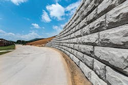
School officials selected a chiseled granite pattern for the concrete components of the new wall. Barger & Sons made 24-square-foot mass extenders in addition to standard-sized blocks and 6- and 3-square-foot pieces for the wall’s top and ends. In total, the company produced 170 precast blocks to cover an area of 2,140 square feet. The wall’s maximum height is 14 feet. It runs for 202 feet.
Midway Middle School
Actual construction of the wall took about two weeks. The contractor’s crew cleared and graded the slope behind the old wall, creating room to pull sections of the old wall back for removal instead of letting them fall onto the road, possibly causing damage to the road surface.
During construction, workers found an old drain pipe that wasn’t serving any purpose. The pipe was holding water beneath poor soil. The sections of soft, unstable soil were removed and replaced.
“We have a lot of clay soils in our area,” says Cole. “We did specify free-draining stone behind the wall because we were, due to site constraints, shoehorning this wall in.”
He adds, “The west side slope is much more gradual. Going to the north side, closer to the property line, the slope steeped up.”
That extra steepness would increase hydrostatic pressure on the wall. Free drainage with sand or stone would prevent this problem. Cole chose to include a stone backfill.
“We filled the top with one foot of clay soil so the grass would grow,” he says. “We added a layer of geosynthetic nonwoven filter fabric to separate the clay from the stone backfill.”
He says that after designing many retaining walls, “nine out of 10 problems I see are because of the type of backfill used [resulting in inadequate drainage].What you use for backfill is critical to the performance of the structure over its lifetime.”
The contractor, Charles R. Blalock & Sons, does many similar projects. To save time installing the backfill, the crew members use a specially designed dump truck. It has a hopper that shoots the gravel directly into the backfill space.
Three years after construction, Midway Middle School’s Stone Strong wall is still standing strong. School buses drive past it daily, and the students riding in them likely give the wall no more than a passing glance. But school officials know they have a well-built, attractive wall that will last for many more years.
Cannon & Cannon of Knoxville, TN, was also involved in engineering work on the project. The firm did civil site design, drawing proposed guidelines for the wall with consideration for the surrounding topography.
The Villages
The Villages is a collection of planned retirement communities set up as separate small towns. They are situated in three central Florida counties and have been gradually developed by the same corporation over a number of years.
One of the earliest Villages communities is about 22 miles from Ocala in Sumter County. The community is in an area where many developers would hesitate to build. The soil is sandy and wet, far from ideal for stability.
In addition to unstable soil, the developers had another significant challenge. They needed to provide a stable road that would cross a large body of water, Lake Sumter, and provide access to the town.
The original plans were to build two bridge structures to support the road. A precast structure placed on top of deep piles at first seemed to offer the best chance of a stable foundation. Instead of following this plan, though, engineers elected to use a 10-barrel, horizontal-ellipse Super-Span system from Contech Construction Products. A major advantage of this system was that the contractor would have to do only minimal preparation below grade before proceeding with the installation.
To go around the Contech bridge structure, engineers chose segmented retaining wall system headwalls made by Keystone Retaining Wall Systems. The Keystone Group of Marietta, GA, supplied the blocks.
The Keystone Country Manor blocks chosen for the project have the appearance of classic stone arch bridges and walls that were built by skilled stone masons in centuries past.
“It’s a random block, and the color is variegated. They didn’t want any pattern,” explains Steve Johnson, estimator for the project’s contractor, Associated Construction Products (ACP) of Lutz, FL.
ACP has built retaining walls at several communities of The Villages. Johnson and ACP’s president, John Bethards, were involved with each project.
To achieve a “tumbled” look, new blocks were put into a chipping-type machine. Johnson says the blocks take on the appearance of much older stones as they get a kind of “instant aging.”
The Keystone Country manor units are textured on three sides. That extra texture allows flexibility in design. Parapets, curves, corners, columns, and other configurations can easily be added.
For the bridges at The Villages, 40,000 square feet of Keystone blocks were installed. They were produced at Big Rock Building Products in Rockwood, TN.
Johnson says that the varying sizes of the blocks added to the difficulty of the work. “Not every block was six by six. They were of various sizes and widths.”
The wall that carries the road over Lake Sumter stands 26 feet at its highest point. It extends 800 feet.
Johnson says the project’s biggest challenge was “keeping the wall vertical as it was being built. We had to start in the center and work out to the ends.” Frequently “checking plumb bobs and laser levels” was essential.
Bethards notes that the crews could not install all of one side of the road and then do the other side. They had to install the headwall in sections—one or two courses at a time—around each of the Super-Span ellipses. After the one or two courses were installed, they were backfilled and then compacted. Then the crew switched to the other side of the road and laid the same number of courses there, backfilled and compacted them, and moved again to the first side of the road to do another headwall section.
The general contractor was Steven Counts Inc. of Summerfield, FL. The project’s engineers were Farner Barley & Associates of Wildwood, FL.
