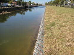
The city of Doral, FL, is facing a two-pronged problem in an extensive drainage canal system. Over many decades, small wave action has gradually eaten away at the canal banks and threatened the integrity of guardrails along a couple of adjacent roadways. Not to be overlooked is the damage the crumbling banks is causing the city’s appearance. Although the canals are actually within Miami-Dade County’s right of way, the city is concerned enough about the aesthetic impact of erosion to embark on a 10-year initiative to stabilize the canal banks with a solution that is both functional and conducive to improving the city’s appearance.
Various streambank stabilization alternatives to the reasonably tried-and-true method of dumping riprap in eroding areas exist, as the city of Doral and others have recently demonstrated. In many situations, engineered systems are a superior-and, when combined with vegetation, often less-costly-alternative to techniques such as placing riprap in unstable areas.
In 2010, the city of Doral began a canal bank stabilization program. The city hired ADA Engineering of Doral and Dunkelberger Engineering & Testing of West Palm Beach, FL, to develop a feasibility study for improving about 11 miles of canals, which originally were constructed years ago for agricultural drainage purposes, according to Alex Vazquez, P.E., civil engineering designer and project manager with ADA Engineering. Vazquez’s employer developed a $4 million, 10-year canal capital improvement plan consisting of canal banks restoration and installation of pedestrian-and-bike path segments along the canal maintenance easements. Gonzalez and Sons Equipment of Medley, FL, was hired to provide construction services.
Years one and two of the project-the former substantially complete as of late spring 2011-cover 2.58 miles of banks along the canals, most of which are 30 to 40 feet wide. The main canal under construction in year one runs from 25th Street to 58th Street, adjacent to 117th Avenue, the first road to the east of the Florida Turnpike. The slope of the banks in all of the canals varies from 1.5 :1 up to 4:1, according to Vazquez. Less-than-ideal soils have led to significant erosion in some areas and made stabilization somewhat challenging, notes Kevin Aubry, P.E., geotechnical services manager with Dunkelberger.
“The soils that were found out there included a couple of feet of man-placed fill over a couple of feet of muck on top of limestone fill,” says Aubry. “The erosion that we saw wasn’t dramatic in terms of overland flow causing major sloughing or even drainage velocities causing erosion. I think it was probably a combination of muck soils and the way the canals were originally constructed” with varying bank elevations, he says. Vazquez adds that owners of surrounding properties were required to retain stormwater on their sites starting back in the 1980s-so, indeed, high-velocity stormwater flows were not a culprit for the erosion. A more likely reason is the fluctuating water levels between wet and dry seasons.
A threat to public safety began to emerge over the years, Aubry and Vazquez note. “In some areas where the guardrail is very close to the top bank, some of the guardrail supports are exposed” on the canal side of the road, says Aubry. “The erosion had actually exposed the posts of the guardrail for long stretches,” Vazquez adds. “There was a concern that if a car hit it, there wasn’t any soil stabilization and the car might go into the channel.”
To stabilize the canal banks, Gonzalez and Sons Equipment installed Presto Products’ perforated Geoweb cellular confinement system components, supplied by R.H. Moore & Associates of Tampa, FL, in a sloped or stacked configuration, depending on the location. In some areas, enough right of way was present to allow sloping; in others, a limestone base was lacking and the Geoweb units essentially form retaining walls.
The Geoweb units are designed to comprise structures that can handle high, intermittent, or continuous flows. According to Presto Products Co., when combined with a turf reinforcement mat (TRM), the vegetated system can withstand velocities as high as 30 feet per second. The voids can be filled with sustainable vegetation, permeable aggregate, or hard-armored concrete to control shearing, lateral, and vertical soil movement. A major feature of the system is the Presto ATRA Key, which connects sections with a turn, forming sections faster than using staplers.
Aubry describes the system as falling somewhere between the categories of soft vegetative systems and hard-armor systems. “It’s kind of halfway between because it’s a form for placement of No. 57 stone,” he says. “I guess if I had to categorize it, I would call it a soft solution; it does have some hard-armor aspects in that you’re placing No. 57 stone in the lower region, and then you have some soil that could be a growing medium in the upper region. It’s also a little more aesthetic than, say, riprap. We were looking for something that was a little more cost-effective and aesthetic. The Geoweb comes in the color green, which is something that the city wanted.” The outer cells of stacked units were filled with topsoil and vegetated.
In some areas, the sloping of the banks presented construction challenges, Vazquez recalls. “If we had to do it all over again, we would probably have tighter cross-sections,” he says, adding that, where needed, construction debris was used as a base material and the areas between the guardrails and canal were cut for Geoweb stacking.
This project demonstrates that different solutions are effective in different situations. “[Streambank stabilization] is not one-size-fits-all,” Vazquez says, adding that stacked Geoweb unexpectedly cost about the same as sloped Geoweb. “There are multiple techniques. In this case, we had two: sloping and stacking. In other locations, those activities may not be feasible.” Adds Aubry, “[Geoweb] can be constructed in areas where you can’t use the sloping method. There were a couple of areas where the drawings showed sloping Geoweb, but we didn’t have enough room to do it that way. It became a matter of, when in doubt, go with the stack.”
Slowing the Flow
Public works managers, engineers, and landscape architects are all too familiar with the effects of nonporous paved surfaces on those that are not paved. A growing volume of upstream nonporous pavements increases runoff and can cause significant erosion and scouring at lower grades.
The experience of the 1,100-acre Prairie Trail planned community in Ankeny, IA, demonstrates the challenges of sustainable development in an area characterized by more conventional development that typically causes increases in runoff. Prairie Trail is being developed with the principle of handling stormwater with a sustainable approach in an area that was undeveloped agricultural land prior to the 1940s. Throughout the 1950s, 180 acres of industrial uses and 120 acres of residential uses were developed in the upper part of a 1,000-acre watershed for a small stream. This stream corridor passes through the center of the new Prairie Trail development.
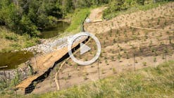
The development that began in the 1950s was one likely contributing factor in increased runoff through the stream corridor, according to the engineer on the project, Greg Pierce, P.E., CPESC, of Nilles Associates in Ankeny. Additionally, heavy tree cover and underbrush had developed in the stream corridor through the years. The tree cover reduced sunlight to the surface, and over time likely eliminated any surface vegetation with deep roots that would have been more erosion resistant, Pierce says. Most likely, the combination of increased and more frequent runoff and the lack of erosion-resistant ground cover led to downcutting and steady streambank erosion over time. A large stretch of the streambank experienced significant erosion, and numerous inland trees were threatened by scouring as well. Corell Contractors Inc. of West Des Moines, IA, was hired to do something about it.
Because of the existence of designated wetlands along the corridor, the $1.14 million project needed to be designed as a restoration project, so hard-armor solutions were a less-desirable option than “softer” ones, Pierce says. Aesthetics also played a role; large areas of revetment stone were not considered desirable, either. Systems were needed at the toe of the disturbed slopes to prevent undercutting and bank erosion until deep-rooted native prairie vegetation could be established. Flow rates and velocities through the corridor were expected to be high enough that the project team sought products that could interlock or be tied together.
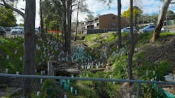
The solution chosen by Nilles Associates was pulling back grades to more stable slopes (3:1 maximum, 4:1 preferred); installing Filtrexx EdgeSaver filter socks and DeKoWe 700 TRM from Belton Industries along gentler bends; and installing Contech Construction Products A-Jacks in a 2:1 triangular configuration along tighter bends. Grade control was achieved by constructing rock riffle dams that used A-Jacks as a “core” to reduce the potential for the dams to be washed out during high flows. The rocks for the riffle dams were placed immediately over the A-Jacks by hand to maintain the integrity of the A-Jacks core. After a protective layer of rocks was installed by hand, additional stones could be placed carefully by small machinery.
The A-Jacks units are high-stability concrete armor units that interlock into a flexible, permeable matrix. They are designed to dissipate energy and resist the forces of flowing water, preventing scour and erosion. The units are installed either randomly or in a uniform pattern, and the voids formed within the matrix provide about 40% open space. The voids actually provide habitat for aquatic life when used as a reef, revetment, or soil support system in river applications. The voids also may be backfilled with suitable soils and planted with vegetation above the normal base flow. Contractors such as Corell can install the units by hand, reducing construction time.
Corell utilized about 8,200 A-Jacks on roughly 3,000 linear feet of the streambank with the units configured in three rows stacked in a two-and-one configuration-that is, two aligned A-Jacks comprise a first and second row near the waterline, and a third row is staggered relative to the other two.
Dan Shell, project manager with Corell Contractors, reports that, even though it was the first time that Corell installed the units, the work was finished in a reasonably short time frame, from fall 2009 to summer 2010. “I would say that this was a unique item for us,” he says of the A-Jacks. “But as we thought through the whole process, we knew that we’ve got great people here and really feel like they can accomplish any task that we present to them, especially if we give them enough time to adjust, and that’s exactly what they did here.”
Still, installing the units required a new approach compared with what the workers were used to, Shell says. “We’re an earthmoving and underground utility company, and we utilize harsh machinery day in, day out to accomplish our work,” he says. “This was a little unique for us because it was a labor-intensive process that required manpower to get it done. We had to tell our guys to get out of the cabs of their machines and get down and dirty.” Pierce notes that Corell Contractors became familiar with how the product fits together, and workers were able to build single runs of 100 to 150 linear feet during the course of a working day.
Several large rains occurred in June and August 2010, including three consecutive nights in August in which up to 5 inches of rain fell in only a few hours. About 120 linear feet, or about 5% of the installed lengths of the streambank A-Jacks, were affected. In two cases, about 20 to 30 linear feet of A-Jacks near the end of the installation rolled over about 80 to 90 degrees because of the churning waters, while most A-Jacks remained locked together, according to Pierce. Repairs to these sections were completed in fall 2010 and involved using the impacted installations as “forms” to place revetment stone material in the voids created by erosion. These repairs cost just over $25,000 to complete, only about 2% of the total project cost. Other practices performed similarly well, Pierce reports. Some revetment material was lost from the riffle dam structures, although the A-Jack cores seemed to reduce losses of this material as compared to previous projects where it was installed without a core. (In one case on this project, the revetment material on a larger riffle structure was displaced completely until the top of the core was reached.) The EdgeSaver socks were seen originally as a temporary measure to protect seeded areas along the shoreline until vegetation was established, but almost all of these installations remained intact, even during the larger rainfall events. Other erosion control measures on the slope pullback areas, such as wattles and TRMs, also proved effective.
Shell concludes that the chosen solution makes sense where site conditions are suitable. “Getting ourselves down to the location was a challenge in and of itself,” he recalls. “We took the time to have a good product installed that’ll last for many years to come.”
A New Approach Saves a Roadbed
When heavy intermittent flows from a stormwater drainpipe caused enough erosion to force closure of a two-lane rural road in Effingham County in southern Illinois, the Effingham County Highway Department needed to get traffic moving again quickly. But, for more than one reason, backfilling the roadbed with riprap and constructing a new concrete box culvert to replace an existing one were not necessarily the right solutions, according to Greg Koester, county engineer.
The drainage structure, located on 1350th Avenue in Summit Township, had formed a deep ditch at the bottom of a steep grade on one side of the road. Scouring had also caused a concrete box culvert to begin to fail, and Koester also considered reconstructing the box culvert. But how long it would take to finish the work with this approach began to weigh on his mind.
“We have a lot of good concrete contractors in the area, and they do their work for a reasonable cost, but I wanted to get something in relatively quickly to open the road back up,” says Koester. “This was kind of a unique situation because there’s no dip in the road to account for this big drainage ditch underneath-the road is nice and flat. The knee-jerk reaction was pricing out a new concrete box culvert, but then as I started looking at the size of the wing walls and headwalls and everything to hold back the roadway, there would have been some pretty sizeable footings. The price began escalating rather quickly, and we were looking at somewhere close to $60,000 to replace this concrete box culvert that failed. I thought that the turnaround would obviously be much quicker if I could put in a pipe.
“So what I did was design a headwall and wing walls out of gabions, and it ended being probably half the price of what a new concrete box culvert with headwalls and wing walls would have cost. We were able to form a drop-box structure for a new corrugated 7-foot-diameter pipe extension on the upstream side, and we allowed that upstream ditch to silt out on its own. Then, on the downstream side, we made a little stair step down. After large rains, we’ve gone down there and checked it, and everything has behaved really well.”
Koester reports that the function of the new upstream gabion structure, built in May 2009, is basically to protect the flow lines. It cost roughly half of what a new concrete box culvert would have cost, or about $34,000 including labor. The structural components used on this project were woven wire gabions from Terra Aqua Gabions.
Filling the ditch with riprap probably would not have been an effective approach, Koester adds.
Often, public works directors solve such problems by installing riprap; however, the force of the flow in this location likely would have overwhelmed even large riprap and sent it downstream, he contends.
“With it being a relatively narrow road and with such a drop, you’ve got to hold that water back,” Koester says, adding that managing water flow on the 2:1 slope without some type of flow-control structure probably would have necessitated a 150-foot-long pipe. “We got away with a 44-foot pipe,” he points out. “We were able to put the wing walls and headwalls around the pipe, and not only that-it was probably a 20-foot drop from the top of the road to the bottom of the drainage ditch. With such a huge drop and a lot of water moving, with all of the scouring, we just had to protect that road.”
About two years after completion of the project, Koester reports that the new gabion structures are maintaining their integrity. It appears that the upstream gabion box structure has not moved, the downstream gabion step structures are keeping the ditch from being burrowed deeper, and the roadway shoulder is not settling.
“There is no exact science with gabions,” concludes Koester. “They only improve your situation. There are always new products on the market, but we’re slowly trying a little bit here and there in a relatively rural county in downstate Illinois. We like them and will use them more and more.”


