Performance of Articulated Concrete Block on Steep Slopes Following Extreme Storm Events

July 1, 2004
By Mike Jacobs, Anne Rotter, Tim Cazier, and Paul Clopper

Cellular articulated concrete block (ACB) systems are flexible concrete revetments used to resist the erosive forces of flowing water resulting from elevated velocities and wave action in concentrated flow areas. A typical ACB revetment mat is formed by interlocking precast concrete blocks placed on a geotextile fabric. The interlocking matrix allows versatile structure design for use over varying land contours and grades. ACBs traverse changes in terrain without disrupting the placement patterns and interlocking features of the system, allowing for partial settlement of the underlying foundation without disrupting the integrity of the installation.

Interlocking ACB matrixThe blocks within the (mat) matrix are dense and durable, and the resulting revetment is flexible and porous (Abt 2001). Voids between blocks allow vegetation to establish over time, decreasing flow velocities and improving final appearance. ACBs became part of the erosion protection arsenal within the past 15 years. In 1999, a hydraulic testing protocol was developed to ensure that each block system will satisfy users’ design needs for stream and river stabilization (Leech 1999). Results of testing these protocols have been published (Abt 2001).This article describes the performance of an ACB system under rugged conditions, steep slopes, and exposure to intense rainfall. The site is the Richmond Hill Mine, located in the Black Hills of South Dakota. The mine is part of reclamation efforts undertaken by Lac Minerals LLC. This site was chosen for study because it has several steep downchute channels protected by ACB, and because several storm events equal to or larger than the design storm event have occurred since downchute construction. The ACB system constructed at this site is Tri-lock produced by American Excelsior Inc. To provide some reference for long-term performance of this relatively new engineering product, the article describes the field performance of the downchutes that have already experienced several extreme storm events, specifically:Localized erosion (causing a ‘bridging’ effect) under block connections and between the geotextile and ground surface; andConcrete cracking and fracturing under extreme weather conditions or during long-term exposure.BackgroundThe Richmond Hill Mine is located in western South Dakota in an area that receives an average of approximately 40 in/yr of precipitation. Golder Associates developed a surface water management plan for the property that included a reclaimed overburden stockpile (ROS). Stormwater runoff is conveyed off the ROS in steep downchute channels armored with Tri-lock.The ROS contains five downchute channels constructed in 1994. Three of these downchutes were inspected by the authors in 2001. Downchutes 1 and 2 are located on the south-facing slope, intercepting runoff from vegetated bench channels at regular intervals. Downchute 3 is on the northwest-facing slope. Specific downchute design parameters are outlined in Table 1.

All downchutes on the Richmond Hill site are armored with ACB and designed to convey runoff from the 100-year, 24-hour storm event of 4.8 inches (Hershfield 1962) and withstand the 100-year design storm event intensity of 1.4 inches of rain in about 25 minutes. (Golder 1997). Tri-lock lock-and-key blocks are manufactured from 4,000 lb/in2 (psi) concrete (AEI). Initial block-production efforts yielded blocks prone to surface chipping and cracking, causing the onsite construction contractor to increase concrete strength parameters. A concrete strength of approximately 4,600 psi was ultimately selected from results of laboratory testing and provided intact individual lock-and-key blocks. The downchutes investigated in this study are armored with Tri-lock blocks casted from 4,600 psi concrete.Installation
The downchute conveys stormwater runoff from the Richmond Hill overburden stockpile.The first step in ACB installation is preparing the foundation. Site preparation is important to ensure adequate performance. The American Excelsior design manual states: ‘Before placing the Tri-lock system, the slope shall be inspected to insure that it is free from obstructions such as tree roots, projecting stones, or other foreign matter. Voids or other soft areas should be filled with suitable materials and well compacted. Although some variation in contour will be allowed, no sudden changes in level can be accepted’ (ErosionWorks 1996). This recommendation was adopted at Richmond Hill.Once the ground surface has been prepared, the geotextile filter fabric is placed. The lock-and-key blocks are transported to the site and manually placed in an interlocking fashion. Finally, the voids are partially backfilled with topsoil to permit vegetative growth. Extreme Events October 1994. On October 5, 1994, Richmond Hill experienced almost 7 inches of rainfall in less than 20 hours (LAC Minerals 2001). Heavy rainfall continued into October 6 but was not recorded because the storm caused a power failure at the site, disabling the rain gauge.May 1995. In May 1995, the property experienced an even higher intensity storm, when nearly 9 inches of rainfall were recorded within a 24-hour period (LAC Minerals 2001). This event nearly doubled the predicted 100-year design event.July 1997. On July 31, 1997, 2.04 inches of rain fell in 25 minutes. The design storm intensity used for the ACB downchutes for this duration storm is 1.4 inches of rain (LAC Minerals 2001). In addition, ‘This event was preceded by significant rainfall during the prior week, which increased antecedent moisture conditions. The structures performed extremely well and only minor repairs were required’ (Golder 1997).June 1998. On June 17 and 18, 1998, Richmond Hill experienced 6.97 inches of rain in approximately 20 hours (LAC Minerals 2001). During the storm, 2 inches of rain fell in less than one hour. CalculationsThe authors performed hydrologic modeling using the May 1995 storm event of 9 inches in 24 hours as a means to gauge the field conditions in the three downchute sections. Results are listed in Table 2.
During this storm event, the downchute sections experienced significantly higher velocities and nearly double the shear stresses of the design parameters listed in Table 1.Observations

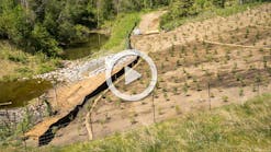
Downchute channel protected by ACBA four-person inspection team consisting of one representative of site management and the authors of this article performed a site investigation, including a detailed inspection of the downchute areas. Notable features included blocks displaying stress cracks after installation. The inspection team performed tests (with a metal probe) between the lock-and-key blocks to determine the presence of voids below the blocks approximately every 10 feet along the downchute length. Overburden Stockpile Downchute ChannelsBeginning on the overburden stockpile, the inspection team examined the downchute channels from the uppermost bench location (initiation point of the ACB portion of the downchute). The downchutes investigated in October 2001 were installed in 1994. The upstream end of the Tri-lock mat was not anchored, but the sides of the downchute mat were anchored into the overburden stockpile cover material. Investigations focused on the blocks in the downchute bed. Site personnel noted that the 4-inch blocks were laid directly onto the geotextile and the open space between blocks backfilled with topsoil. Visual inspection indicated a good vegetative cover including 12-inch-high grasses in the downchute bed. In fact, much of the Tri-lock mat was obscured due to the dense cover.

Typical sideslope termination with sides of mat anchored into the stockpile
Typical installation processBetween the first and second bench, the mat was more visible. The geofabric was intact and resistant to penetration with a sharp metal probe. The open spaces between the blocks displayed good vegetative cover. Few cracks and no block breakages were observed. One spot of bridging was observed: a 2-inch-diameter void space between the geotextile and underlying rock. The void was a half-inch depression. Immediately above the second bench channel, the first crack was observed in a key block. Continuing down the first downchute channel, the inspection team observed:One broken lock block adjacent to one broken key block approximately 20 feet downstream of the final bench channel. The blocks, though broken, were clearly still locked into the Tri-lock mat matrix and were not protruding above the mat surface. Vegetation was rooted in the crack between the broken pieces; andOne cracked key block approximately 50 feet from the downstream-most end of the downchute channel.The northwest downchute channel (Downchute 3) is the steepest of the downchutes at approximately 2.5H:1V. The mat is notably less uniform in this section, and the blocks display more cracks. One broken and one cracked key block were found approximately 5 feet from the bottom of the downchute. All blocks in this section (including the damaged blocks) remained locked into position and remained a functioning part of the mat system. The inspection team was unable to dislodge even the protruding blocks using the metal probe as a lever.While testing approximately every 10 feet down the downchute, the probe did not reveal any other voids below the block mat or any voids between the geotextile and underlying prepared surface.Three protruding blocks were noted on the second downchute. The protruding blocks were not accompanied by voids and were not dislodged by probing with the metal lever. This downchute channel also contained a cracked block directly upstream of a 1.5-foot-diameter boulder lying in the downchute bed. At one location in this downchute the inspection team noticed an area marked by several broken and cracked blocks. There was an apparent ‘hole’ in the mat and a 2-inch void beneath one of the broken blocks. Mouse droppings surrounded the area, and the inspection team concluded that the mice caused the voids and perhaps compromised the integrity of the base material, causing additional stresses in this location. Nevertheless, the blocks in this area were not dislodged or protruding above the plane of the mat. Site personnel indicated the condition at this location was first noticed after the intense storm in 1997. Field inspection after the storm noted that the blocks remained securely in place.Summary
Vegetation cover in the bed of Downchute 3Of all of the ACB downchutes inspected, site personnel indicated that only one block had been ‘tamped back down into place’ during a routine inspection of the downchute channels on the waste dump surface since installation. Overall, less than 1% of the blocks investigated were cracked or broken, and in the areas showing stress cracks or fractures, less than 10% of the surface area was affected. The damaged blocks remain in place and function as part of the ACB erosion prevention mat. ConclusionsObserving and documenting the condition of installed ACB products is an important means to understanding field performance and provides valuable information for future design applications. The conclusions from this study are these:Tri-lock system integrity is stronger than the integrity of individual blocks because the system can function properly even in areas marked by cracked and broken block pieces. The pieces remain a part of the mat, held in place not only by the interlocking nature of the product but also by backfilled and deposited soil and the root systems of established vegetation. Because each block interlocks with its neighboring blocks, it forms a total membrane, ‘allowing the entire revetment to act as one’ (ErosionWorks 1996). Good quality assurance on foundation preparation is critical for long-term durability of the mat systems. Continuous contact between the ground surface and the geotextile, and between the geotextile and the blocks, allows the system to function optimally.Channel slope is a factor in the durability of ACB systems as shown by downchute sections that experienced the same volumes of water: Higher velocities in the steeper channel sections (2.5H:1V) caused more stress cracks and block breakages. Nevertheless, the mat remained intact and the channel functional through the extreme storm events. Localized failure in the downchute bed did not cause failure of the downchute system during the storm events experienced.Natural forces other than rainfall events, such as boulders moving down the downchute bed and debris flows or invasive animal activity can also cause damage to the ACB mat. Again, fractures and block breakages caused by such occurrences did not cause failure of the mat system. As concluded in the studies related to ACB testing protocol, ‘Stream bank or embankment stability is directly linked to the interaction of the block foundation, filter, block size, block void space, block weight, and degree of articulation’ (Leech 1999). Field reports support these findings and further provide evidence of the longevity and stability of articulated concrete products despite experiencing storm events where total rainfall and rainfall intensity were higher than design values. Mike Jacobs, P.E., is a principal and Anne Rotter, P.E., and Tim Cazier, P.E., are project engineers with Golder Associates Inc. in Lakewood, CO.

Paul Clopper, P.E., is manager of Water Resources for Ayres Associates in Fort Collins, CO.