Pipes, Culverts, and Detention Systems
When it comes to managing stormwater runoff, concrete, corrugated steel, and plastic pipes all have their place. The following three projects highlight the opportunities of using pipe for both conveying runoff and detaining it.
In the first, very challenging, project, engineers in San Francisco used concrete pipe to build an auxiliary sewer pipe system, which was layered under a busy thoroughfare between utilities and a subway line. Installers dealt with a confined area that required the pipe to be delivered as it was needed.
In the second project, engineers in Chicago had the challenge of designing a system to manage the drainage for an entire paved city lot. They came up with a solution that took advantage of the native soil and used plastic pipe to both convey and detain runoff.
And in the third project, which ran more than 8 miles across two counties in North Dakota, landowners, the local water board, and government agencies at the local, regional, and federal levels all worked together to come up with a way to drain thousands of acres of farmland, some of it under as much as 20 to 25 feet of standing water, using corrugated steel pipe.
The Chavez Sewer System Improvement Project
Retrofitting a post-1906-earthquake-era sewer system, especially one that lies between underground utilities and a subway line on a main thoroughfare, isn’t a project to be undertaken lightly.
The retrofit was prompted by a 100-year storm on February 25, 2004, which resulted in side streets along the thoroughfare, the Cesar Chavez corridor, filling with up to 4 feet of standing water.
“The rain gauge at Mission Education Center recorded 1.38 inches in one hour in the morning,” says Wallis Lee, the San Francisco Department of Public Works (SFDPW) hydraulic engineering group lead. “The total depth for 24 hours was approximately 2.53 inches.”
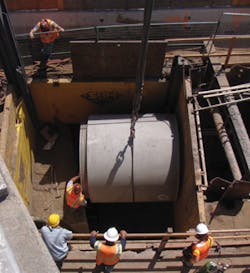
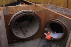
A section of reinforced concrete pipe being lowered into the trench for installation
The corridor lies on relatively flat land between 20 and 70 feet above sea level. San Francisco’s famous hills rise as high as 700 feet upstream. Also upstream is an almost-800-acre watershed. Before the project, it would take very little rain before the runoff would flood local basements, and where Cesar Chavez Street flattens out, the flow depth increased.
One of the main objectives of the project was to improve the conveyance of stormwater during extreme storm events, Lee says. Another was to increase the reliability of the combined sewer system. The retrofit included installing auxiliary pipe alongside the existing vitrified clay sewer pipes as well as relining the existing brick sewers.
The San Francisco Public Utilities Commission (SFPUC), which owns and operates the sewer system, specified reinforced concrete pipe (RCP) for the auxiliary pipe, primarily because the area has a very high water table and flotation could have been a problem with a lighter-weight material.
Through the awarded contract with JMB Construction, the city used pipe from nearby Piranha Pipe and Precast in Chowchilla, CA, which had the required diameters of pipe readily available.
SFDPW provided the design and construction management services. After geotechnical investigation showed that groundwater was absent and that the soil was cohesive, SFDPW specified various forms of construction methodologies. These included open-cut operation, trenchless operation, and trenchless rehabilitation operation.
One reason for trenchless operation and trenchless rehabilitation was that they minimized the disruption to the public transportation system aboveground. Open-cut installation would have required overhead electric wires to be de-energized and diesel buses substituted for light rail vehicles.
Another reason was that the pipes could be installed without interfering with the many utilities within the sewer trench. And third, because the water table is high in this area, the soil over the subway tunnel keeps the tunnel from wanting to uplift. Removing the soil would have removed the loading and might have caused movement in the foundation of the tunnel.
A significant challenge was the constraint in the design depth. The bottom of the tunnel had to be at least 6 feet above the top of the subway structure, and the top of the tunnel had to be below a depth of approximately 20 feet to avoid the utilities under the street.
“The depth was selected for the downstream tie-in point and typically a few feet above the top of the pipe to the bottom of other utilities encountered across the trench,” explains Lee. “The bottom of the auger hole is still a few feet above the top of the subway tunnel.”
The project took approximately two years. The notice to proceed came in June 2011, and the project was completed in April 2013.
During construction, two lanes of traffic in each direction were open at all times. Heavy equipment, including a crane with a long boom, was onsite. Because of the very limited storage area, the pipes were delivered and installed in sequence.
JMB Construction Inc. of South San Francisco excavated to a depth of 20 feet along approximately 6 blocks of Cesar Chavez Street. Crews installed the shafts and shored up the sides of the trench to support both the trench and the bore and jack operation, the method of trenchless installation.
In this operation, an auger head tunnels in, dirt is removed, and the pipes are pushed into place by a jacking pipe, Lee explains. The diameter of the jacking pipe matches the diameter of the pipe.
JMB continued to lay pipe in parallel with the trenchless operation.
Downstream, crews used 1,974 feet of 72-inch pipe and 3,093 feet of 84-inch pipe. Upstream, they used 48-inch pipe. The selection was based on the size of existing line next to the auxiliary pipe, the amount of anticipated storm runoff, and the slope.
The smaller, local pipes are egg-shaped vitrified clay, a blend of clay and shale. They range in size from 2 feet by 3 feet, to 3 feet by 4 to 6 inches. JMB connected these pipes to the round auxiliary pipes at cast-in-place junction structures with manhole access openings.
Some of San Francisco’s existing brick sewers had been mortared previously with a layer of concrete. As part of this project, all the brick sewers within the project limits were lined. They could have collapsed during an earthquake event, Lee notes. Lining them provides a new surface inside the pipe as well as increases the longevity of the sewer.
“We lined them as part of the project because of the synergetic opportunity while performing this large-scale operation. The overall system needs to work as a whole with the new facilities under this project.”
InsituForm, an international company with its headquarters in St. Louis, MO, produced the cured-in-place pipe (CIPP). SAK Construction LLC, based in O’Fallon, MO, did the installation.
After construction, JMB removed the shoring and filled any spaces between the edges of the tunnel wall and the pipe with grout, which was pumped in through small port openings located in the wall of the pipe.
“I’m pleased with the way the project went,” says Lee. “After construction, no repairs were needed to the subway line or utilities. The project as designed has been performing as well as we expected, especially during the December 2014 storms, which were almost as intense as the February 2004 storms.”
The 63rd Street Infiltration/Detention Project
The Intermodal Rail Yard on 63rd Street, a few miles south and west of Chicago, has been a fully functional intermodal facility for transferring containers of freight between trains and trucks in and around the city and the region for decades.
“The yard had been operating for a long time, but it hadn’t been paved,” says Eric Chow, a project engineer with Patrick Engineering in Chicago. “The surface was broken asphalt and millings, piled up and leveled out to provide a place for trucks and trailers to park. Not a lot of stormwater could infiltrate for water quality.
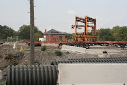
Large-diameter corrugated HDPE pipe waiting to be installed at a depth of 13 feet. Long-term settlement in the sandy soil was not a concern because of the pipe’s light weight. The orange structure in the background is the side loader that moves containers on and off trucks and rail cars.
“They were gradually adding fill to the yard and it was causing flooding problems for the neighbors immediately to the east, a CTA
[Chicago Transit Authority] light rail facility and an apartment complex. They were having flooding from this yard about once a year.”
When the owner of the yard, Norfolk Southern Railway Co., planned a retrofit, primarily to modernize the gate system, the project included paving the entire 47-acre site.
The infiltration/detention project was designed to meet the city’s requirements to detain runoff and improve water quality. It uses permeable pipe to drain the entire site: the loading and unloading areas for inbound and outbound freight trains, the drive aisles, and the chassis storage areas, as well as under the containers and the side loaders that load and unload the trains.
“The fact that we couldn’t put in a pond was challenging, but we wanted to maximize the available footprint for parking,” says Chow.
One of the main drivers for the use of permeable pipe was the native sandy soil. Percolation tests in three different locations found that between 8 and 32 inches of runoff infiltrated in an hour.
“The site is pretty close to the lake and the soil is very good for infiltration,” he says. “We wanted to use that native soil as much as possible.”
The pipe has to withstand a tremendous amount of weight. Some 175,000 containers pass through the yard every year, with 12 inbound and 10 outbound trains, seven days a week.
Norfolk Southern specified N-12 corrugated perforated HDPE pipe made by Advanced Drainage Systems, Inc. (ADS) in Hilliard, OH.
“The railroad likes using HDPE, especially from ADS. They used it under their rail facility,” says Chow. The reasons include its strength and cost, and the ease of installation and shipping. In addition, because HDPE pipe is lightweight, there was no concern about it settling in the sandy soil.
Although the surrounding area is built up, runoff on this side of the yard comes predominantly from onsite because stormwater infiltrates in the rail yard to the west.
Chow and his team designed surface ponding in the parking areas to a maximum depth of approximately 1 foot, for a 100-year storm. It will draw down relatively quickly.
They also designed an infiltration vault system, which they oversized to provide for future expansion for a small lot about a block away. The system is a configuration of three systems of pipe in different areas of the site for a total footprint of 84,000 + 20,000 + 28,000 square feet. This underground infiltration provides approximately 156,000 cubic feet of storage.
RT Milord Company of Bridgeview, IL, was the general contractor for the project.
The underground work began in the fall of 2012 and was completed in 2014. Time was a constraint by the end of 2013.
“This is one of the main shipping facilities for UPS,” says Chow. “We were trying to get things done before the holidays. Most of the yard was in operation during construction. The contractor staged the parts that would stay open and closed.”
Crews excavated to 13 feet. “Cover was an issue,” he says. “To provide enough strength, we had to design for heavy-duty loading.” Pipe of two different diameters was used: 7,600 feet of 24-inch pipe, and 2,500 feet of 36-inch pipe. One of the reasons was to balance the three systems. The other was because of constraints by the outlets to the city’s combined sewer system.
The pipes were wrapped in geofabric to keep out fines, and then placed in an aggregate trench. The aggregate provides additional strength and helps with infiltration.
Because of the extreme loading on the surface, Chow used precast concrete manifolds instead of HDPE pipe headers to connect the systems. He also used manhole covers designed for airports.
“This was definitely a unique project,” he says. “I hadn’t worked on something that large and constrained before. The system is working well. We had a meeting with the locals and the residents of the adjacent apartment building, and there were no complaints about flooding.”
Michigan Spillway Flood Control Project
Vast amounts of moisture—both heavy snow and rainfall—have been falling on the flat, rural Red River basin in North Dakota and Minnesota for the past 25 years, says Ben Varnson, chairman of the Nelson County Water Resource District in North Dakota.
Ten inches of rain can fall during the spring thaw, when the snowpack is melting. And because the Red River flows north to Canada, where the channel remains frozen for longer, the water has flooded the basin in the two states.
To make matters worse, 50 square miles of the watershed lie to the north of northern Nelson County, “and when you live at the bottom end of a watershed, you get runoff from the upper reaches watershed as well as from stormwater here onsite,” says Varnson.
“There are 48,000 acres in our county,” he adds. “Until the early ’90s, approximately 400 acres were covered with water all year. For the last 15 years, 24,000 acres have been covered all year by water that ranges from two inches deep to 25 feet deep.”
The results are flooded basements, impassable roads, and farmland that is underwater all year round in the northern part of Nelson County, including the city of Michigan and portions of Michigan, Rubin, Enterprise, and Sarnia townships. Out of 12 farmsteads in the area, only two are habitable.
“We need to get the water off this land and get our folks back up to speed,” says Varnson. “It will take five or more years to accomplish.”
Since the late 1990s, landowners, the townships, and county entities all have been working toward a solution. There are already several drainage ditches across county, but the body of water that needs to be drained isn’t connected to any of them. All the land is privately owned.
The Michigan Spillway Flood Control Project, a flood damage control initiative, realigned the existing ditches and connected them to one another. The completed
channel meanders 8.03 miles across the basin, following the contour of the land. It begins in a field in Enterprise Township and ends at Dry Run Creek, a tributary of the Middle Branch Forest River in Sarnia Township.
Once the project is complete, the ditch will divert the water away from the city of Michigan and relieve about 40,000 acres of agricultural and roadway flooding in the county. In doing so, it will recreate more than 60 wetland basins as a secondary benefit.
Because the bottom of the ditch was water bearing, no aggregate was used; the sand filled in around the pipes.
Olson Engineering of Devil’s Lake did the engineering for the project. Because most of the soil is clay, in some pockets 8 feet deep, the majority of the ditch is open design. In other areas, though, especially where the elevations are higher, the soil underneath is a less-stable sandy clay and requires pipe. One roadway also required pipe.
“We were looking at all kinds of piping material,” says Varnson. The choice was Aluminized Type ll coated corrugated steel pipe manufactured by TrueNorth Steel, which has its corporate office in Fargo. “They gave a potential lifetime use of 60 to 70 years.”
The permitting process was extensive and included local, state, and federal agencies, especially the US Fish and Wildlife Service, the Army Corps of Engineers, and the North Dakota State Water Commission.
Because the proposed flood channel was located in an existing 40-year-old drainage system, but with a 5-foot-deeper cut, there were two major concerns. One was that it might have an impact on protected wetlands. Sections of pipe were placed in these areas. The other concern, that invasive species of fish downstream could migrate into the area, will be resolved with the expansion of an existing pump station.
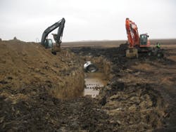
The surveying began in 1996. Johnson Excavating in Petersburg began work in late December 2013—not the best time to be in the field in North Dakota, says Keith Fraase, a civil engineer with TrueNorth Steel. “At that time of year, a large part of the ground is frozen, but once they dug below that, they were working in wet ground.”
Johnson dug an average of 11 feet, and 22 feet deep on the higher land. Crews placed a total of 5,700 linear feet of 72-inch-diameter (81-inch by 59-inch) arched, aluminized corrugated steel pipe. This pipe has 5-inch by 1-inch corrugation.
An advantage of steel pipe is that it can be shipped in long lengths, which reduces freight costs and joint connections. This pipe is 48 feet long. It has access points every 400 feet for ventilation and cleanout.
“They had to put it in quickly,” says Fraase. “The bottom of the ditch in those places is water-bearing sandy clay soil.”
The soil filled in around the pipes, eliminating the need for aggregate. The amount of cover varies throughout the project between approximately 5 and 15 feet.
Along the open parts of the channel, crews used the native clay soil for the 12- to 16-foot bottom width and for the side slopes, which are 3:1 in most places and 4:1 along roadsides.
“It’s pretty much flat land, and there isn’t a lot of flow,” says Fraase. “There won’t be flooding in the channel.”
The spillway project also enlarges an existing pump station about 4 miles from the beginning of the channel, which was necessary because of the flat topography. The water district is still using temporary pumps until the project is completed.
“We may need additional grants to finish the project,” says Varnson. The cost of materials has increased since the original cost share was approved; a route was realigned because of landowner and permitting issues; land costs were higher than anticipated; and there were unanticipated permitting, consultant, and project modifications required to secure the US Army Corps of Engineers 4O4 permit.
“Once we got through the permitting process, the project went fairly smoothly,” he says. “The members of the water board have a passion to make a difference. Landowners, local and regional officials, legislators, and the state water commission worked with us to get this accomplished. They all get credited for their help.”
Strength Under Pressure
Strength is of the essence when underground pipes and storage chambers must bear heavy loads, especially when the logistics of a project limit burial depths. Two new stormwater chambers have been designed to meet the challenge. Prinsco Inc. and Lane Enterprises have launched stormwater chambers built from the same design, which they co-developed. The high-performance, injection-molded chambers will be sold by Prinsco as the HydroStor line and by Lane as the StormKeeper line.
The chambers are engineered to meet or exceed ASTM F2418, the Standard Specification for Polypropylene Corrugated Wall Stormwater Collection Chambers. The larger chamber stores 180 cubic feet of stormwater per chamber and the smaller 75 cubic feet per chamber. The chambers are ideal for large civil commercial construction projects.