Water Meter Design Plays a Major Role in Returning Accurate Readings
In Part 2 of this three-part series, authors Adam Kozlowski and Janusz Dubicki continue this study of magnetic field interference and discuss how to measure residual magnetism in commercial and residential water meters. With a greater understanding of residual magnetism and the use of magnetic field indicators, our author illustrates how these adverse effects on the measuring capacity on water meters and other utility devices can be monitored as well as minimized.
Crime Stopper (Part 2)
by Adam Kozlowski and
Janusz Dubicki
The fight against water theft with the use of strong magnetic field
How do you protect your meter network from losing its measuring capability? One option to improve and protect measure devices like dry-dial water meters is to use passive magnetic field indicators to detect the action of a strong magnetic field primarily coming from neodymium magnets. These indicators are especially useful for water meters already in use in networks (external installation), but in the case of new water meters, the passive magnetic field indicators can, by design, be installed also inside the device. The indicators are also used to detect a strong magnetic field action on other vulnerable measuring devices, like watt-hour meters and gas meters.
Measurement of Residual Magnetism
The influence of magnets on dry dial water meters can lead to the magnetization of some of their parts, like: circlips, magnetic screens (when materials are wrongly chosen), and other ferromagnetic construction members. To detect the magnetization of ferromagnetic elements in a measuring device by a neodymium magnet, electronic meters applying Hall sensors or magnetoresistors are often used (Hall effect magnetic field meter of SMS-102 type 2003).
Crime Stopper (Part 2) by Adam Kozlowski and Janusz Dubicki
The fight against water theft with the use of strong magnetic field How do you protect your meter network from losing its measuring capability? One option to improve and protect measure devices like dry-dial water meters is to use passive magnetic field indicators to detect the action of a strong magnetic field primarily coming from neodymium magnets. These indicators are especially useful for water meters already in use in networks (external installation), but in the case of new water meters, the passive magnetic field indicators can, by design, be installed also inside the device. The indicators are also used to detect a strong magnetic field action on other vulnerable measuring devices, like watt-hour meters and gas meters. Measurement of Residual MagnetismThe influence of magnets on dry dial water meters can lead to the magnetization of some of their parts, like: circlips, magnetic screens (when materials are wrongly chosen), and other ferromagnetic construction members. To detect the magnetization of ferromagnetic elements in a measuring device by a neodymium magnet, electronic meters applying Hall sensors or magnetoresistors are often used (Hall effect magnetic field meter of SMS-102 type 2003). [text_ad] Methods used for the magnetization state measurement (residual magnetism) cannot be treated as court evidence because of technical circumstances: They do not give reliable information on the source of the magnetic field that was used (if the magnetic field influenced the correct measurement made by the meter), and, first of all, the “history” of measuring devices is not known in most cases, i.e., if their parts could have been under the influence of magnetization before the installation of the dry dial water meters in networks. Most objects made of ferritic steel in our surroundings are characterized by residual magnetism, which can be detected by using electronic measuring devices with Hall sensors or magnetoresistors even though nobody put a neodymium magnet to these objects. For example, scissors, after some time, can attract paperclips. Residual magnetism is also formed in many steel elements because of mechanical stress, e.g., in production processes. That is why many meters, even during the time of delivery, can be magnetized. Detected magnetization can also be caused by using a weak ferrite magnet, to which dry dial water meters should be resistant (according to the EN 14154 standard [Water meters–Part 3: Test methods and equipment 2005]). [caption id="attachment_3382" align="alignright" width="270"]Methods used for the magnetization state measurement (residual magnetism) cannot be treated as court evidence because of technical circumstances: They do not give reliable information on the source of the magnetic field that was used (if the magnetic field influenced the correct measurement made by the meter), and, first of all, the “history” of measuring devices is not known in most cases, i.e., if their parts could have been under the influence of magnetization before the installation of the dry dial water meters in networks. Most objects made of ferritic steel in our surroundings are characterized by residual magnetism, which can be detected by using electronic measuring devices with Hall sensors or magnetoresistors even though nobody put a neodymium magnet to these objects. For example, scissors, after some time, can attract paperclips. Residual magnetism is also formed in many steel elements because of mechanical stress, e.g., in production processes. That is why many meters, even during the time of delivery, can be magnetized. Detected magnetization can also be caused by using a weak ferrite magnet, to which dry dial water meters should be resistant (according to the EN 14154 standard [Water meters–Part 3: Test methods and equipment 2005]).
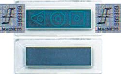
a) Before magnetic field action—multi-domain structure visible in form of geometric figures
b) After magnetic field action with strength over 3.52 kOe (280 kA/m); single-domain structure ”lack of geometric figures
(Source: European Community Design No. 000485487 2006; www.magneto.pl/en/page/136)
Even if a method of residual magnetism measurement can definitely show that a neodymium magnet was used, there is an easy way to remove residual magnetism from ferritic steel elements by using an alternating, decaying magnetic field, which can be created by a rotating magnet used to stop measuring process of dry dial water meters.
Passive Magnetic Field Indicators
A passive magnetic field indicator uses a magnetic domain pattern method. By affecting measuring devices with a strong magnetic field, it is possible to observe changes in the domain pattern of the magnetic field indicator (Figure 4) [Addressing an EMC weakness due to strong static magnetic fields 2007]. One can obtain the domain structure of the indicator through magnetization in a multi-pole circuit. This structure is visible by using a special magnetic film reader, which polarizes in a magnetic field according to Bitter patterns (Hubert, A., and R. Schaefer 1998).
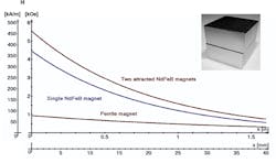
The indicator, having a hermetic, transparent casing, is in the form of a sticker, which can be easily installed on measuring devices. When a magnetic field of the appropriate strength of about 3.52 kOe (280 kA/m)—e.g., coming from a neodymium magnet (Figure 2)—affects the indicator, then the multi-domain structures (geometric figures) of the indicator are re-magnetized—the light green contours of the magnetic geometric figures become irreversibly blurred or the figures disappear completely (Figure 4b).
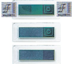
In the case of measuring devices, which additionally need the detection of a lower magnetic field strength, one can use the two-threshold magnetic field indicator (Figure 5).
The magnetic field indicator is divided into three fields: a dark green reference field, a light green field, and a field with a magnetic geometric figure (a triangle, circle, or square with a circle inside each figure) with a light green contour on a dark green background. When a magnetic field of a strength over 0.1 kOe (8 kA/m) (e.g., coming from a neodymium magnet placed at a distance of a dozen or so centimeters from the indicator, or a ferrite magnet placed at a distance of a few centimeters from the indicator) has acted on the indicator, the light green field irreversibly changes its color into dark green, equal to the color of the reference field (Figure 5b). When a magnetic field of a strength of about 3.52 kOe (280 kA/m) (e.g., coming from a neodymium magnet placed at a distance of a few millimeters from the indicator) has acted on the indicator, the light green contours of the magnetic geometric figure become irreversibly blurred, or the figure disappears completely (Figure 5c).
a) Before magnetic field action
b) After magnetic field action with strength over 0.1 kOe (8 kA/m)
c) After magnetic field action with strength over 3.52 kOe (280 kA/m)
(Source: www.magneto.pl/en/page/136)
The two-threshold magnetic field indicator MFI-4 can be used in devices, which, because of their design, would need a few MFI-3 indicators or in devices, which are also sensitive to magnetic fields from weaker magnets, e.g., ferrite or AlNiCo magnets.
The magnetic field indicators MFI-3 and MFI-4 have been designed in two versions:
To install on internal surface of transparent casing of measuring device
To install on external casing surface of measuring device
The latter version of indicators MFI-3 and MFI-4 requires additional mechanical protection in the form of holograms, with logo, name, serial number, code, etc., applied on one or both the indicator side wings (Figure 4a and 5a). The holograms are characterized by so-called self-destruction (each attempt of removal from the surface they are applied to causes their destruction that indicates mechanical tampering).


